
composite forming machine

A composite material and forming machine technology, applied in punching machines, presses, manufacturing tools, etc., can solve the problems of not finding composite forming machines, irregular shapes, and high production conditions, achieving small strokes, simple control, and responsiveness. fast effect

Active Publication Date: 2019-12-20
JDM JINGDA MASCH (NINGBO) CO LTD
View PDF7 Cites 0 Cited by
  • Summary
  • Abstract
  • Description
  • Claims
  • Application Information

AI Technical Summary

Problems solved by technology

[0002] Composite molding machines generally include sliders, bases, pressurized cylinders, worktables, upper molds, lower molds, and lifting cylinders. However, because the shapes of products produced by them are usually irregular, the production conditions are better than those of existing injection molding machines and presses. The requirements are high, and it is also necessary to shorten the molding time, improve the molding quality and automation. Long-term research has been conducted on this, but a composite molding machine that better meets the needs of actual production has not yet been found.

Method used


Image

  • composite forming machine
  • composite forming machine
  • composite forming machine

Examples


Embodiment Construction

[0020] The present invention will be further described below in conjunction with the embodiments of the accompanying drawings.

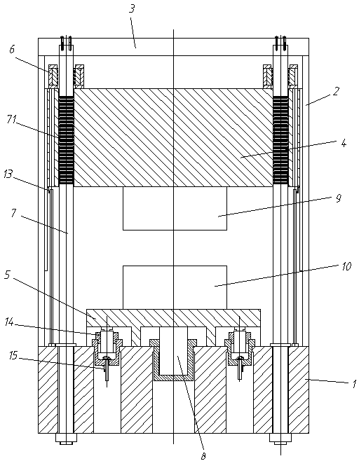
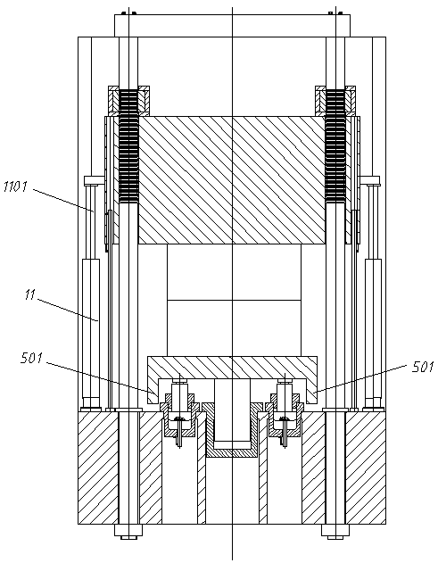
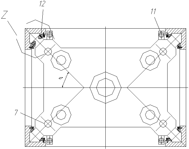
[0021] Such as figure 1 , figure 2 As shown, a composite material forming machine includes a base 1, a frame 2, a top seat 3, a slider 4, a worktable 5, a brake mechanism 6, a pull rod 7, a pressurized cylinder 8, an upper mold 9, and a lower mold 10 , lifting oil cylinder 11, leveling oil cylinder 14.

[0022] The above-mentioned top seat 3 and the base 1 are supported by the surrounding frame 2 to form a sliding block guide frame of the composite material forming machine.

[0023] In the above-mentioned frame, the above-mentioned workbench 5 is arranged on the base 1, the lower mold 10 is installed on the workbench 5, the upper mold 9 is arranged above the lower mold 10, and the upper mold 9 is installed on the bottom surface of the slide block 4.

[0024] The upper end of the pull rod 7 passes through the top seat 3 and is fixed together with ...


PUM


Abstract

A composite material forming machine comprises a bottom seat, a rack, a top seat, pulling rods, a slide block, locking mechanisms, a pressurizing oil cylinder, a worktable, an upper die, a lower die and lifting oil cylinders, wherein the lower die is arranged on the worktable which is positioned on the bottom seat; the upper die is arranged above the lower die and is mounted on the slide block; two ends of the pulling rods are correspondingly fixed to the bottom seat and the top seat; the slide block passes through the middles of the pulling rods; the locking mechanisms are arranged between the slide block and the pulling rods; the locking mechanisms are arranged on the slide block and can be used for locking or unlocking the slide block and the pulling rods from relative movement; the pressurizing oil cylinder is arranged on the bottom seat; the lifting oil cylinders are arranged on the bottom seat, and piston rods of the lifting oil cylinder are fixed to the slide block; a control system is arranged to control the lifting oil cylinders, the locking mechanisms and the pressurizing oil cylinder in a following manner: the locking mechanism unlocks the slide block while the slide block quickly lifts up and down, and the slide block is lifted through the corresponding lifting oil cylinder until an upper die block and a lower die block are separated or combined; and the locking mechanisms can lock the corresponding pulling rods when the dies are pressurized, and the lower die is pressurized through the corresponding pressurizing oil cylinder.

Description

technical field [0001] The invention relates to a composite material forming machine. Background technique [0002] Composite molding machines generally include sliders, bases, pressurized cylinders, worktables, upper molds, lower molds, and lifting cylinders. However, because the shapes of products produced by them are usually irregular, the production conditions are better than those of existing injection molding machines and presses. The requirements are high, and it is also necessary to shorten the molding time, improve the molding quality and automation. Long-term research has been carried out on this, but a composite molding machine that better meets the needs of actual production has not yet been found. Contents of the invention [0003] The technical problem to be solved by the present invention is to overcome the above-mentioned defects of the prior art and propose a composite material forming machine so that it can better meet the actual production needs. [000...

Claims


Application Information

Patent Timeline
Patent Type & Authority Patents(China)
IPC IPC(8): B30B1/32B30B15/24B29C70/54
CPCB29C70/54B30B1/32B30B15/245
Inventor 叶文聪许骏郑良才殷莎
Owner JDM JINGDA MASCH (NINGBO) CO LTD
Learn More