Launching frame and system for launching unmanned aerial vehicle

A catapult, UAV technology, applied in the field of UAV launch, can solve the problems of partial weight, cumbersome, narrow range of use, etc.

Active Publication Date: 2017-02-22
北京韦加智能科技股份有限公司
View PDF9 Cites 8 Cited by
  • Summary
  • Abstract
  • Description
  • Claims
  • Application Information

AI Technical Summary

Problems solved by technology

[0003] This kind of elastic rope ejection frame has the following problems: First, because the energy storage of the elastic rope is a form of stretch-denatured energy storage, long-term use will cause the aging of the elastic rope, which will affect the elasticity and firmness
At the same time, the temperature environment also has a great influence on the performance of the elastic rope. When the ambient temperature is low, the elastic rope is more brittle, and when the temperature is too high, the elastic force will decrease; Dead joints, so when the ejection weight

Method used


Image

  • Launching frame and system for launching unmanned aerial vehicle
  • Launching frame and system for launching unmanned aerial vehicle
  • Launching frame and system for launching unmanned aerial vehicle

Examples


Embodiment 1

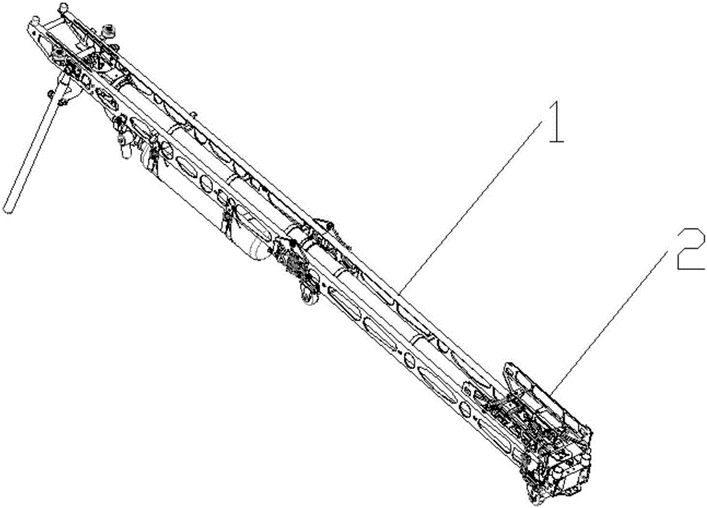
[0037] Such as figure 1 As shown, the present embodiment provides a catapult for unmanned aerial vehicles, which includes a catapult body 1, a sliding frame 2, an ejection rope and a driving device; the catapult 2 is arranged on the catapult On the body 1, it is used to carry and launch the unmanned aerial vehicle; the ejection rope is arranged at the launching end of the ejection frame body 1, and the sliding frame 2 is arranged at the initial end of the ejection frame body 1, and can be The extension direction of the ejection frame body 1 slides; the driving device is connected with the sliding frame 2 for driving the sliding frame 2 to move along the extension direction of the ejection frame body 1, so that the sliding frame The running frame 2 collides with the ejection rope to launch the unmanned aerial vehicle.

[0038] It uses the driving device to drive the sliding frame 2 to move on the ejection frame body 1. When the sliding frame 2 collides with the ejection rope, ...

Embodiment 2

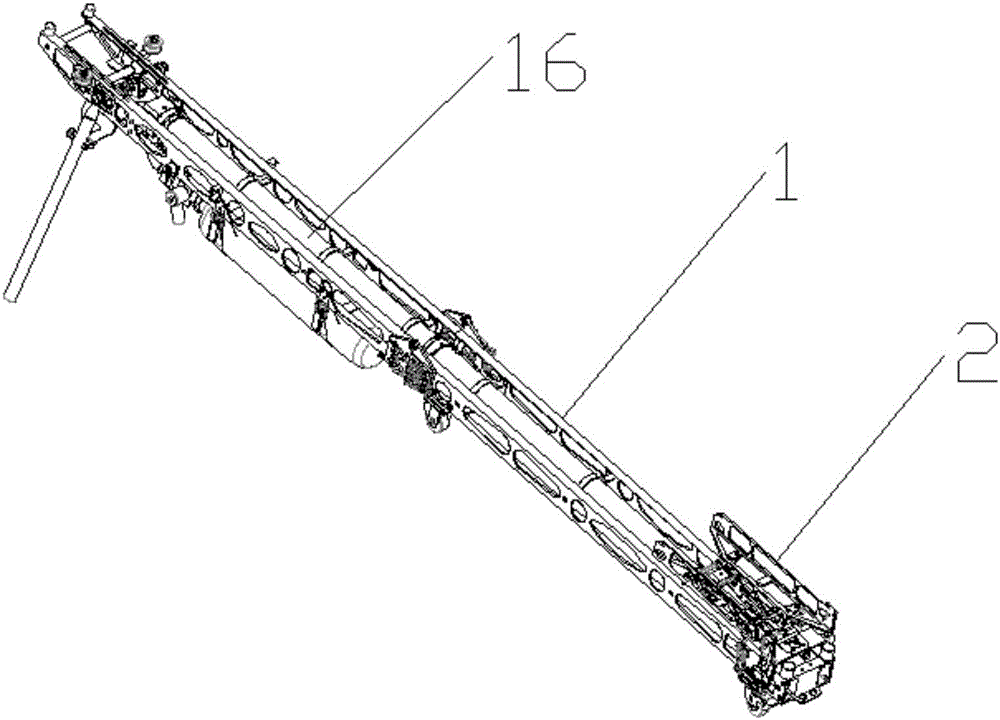
[0040] Such as Figures 2 to 4 As shown, the present embodiment provides a launch frame for unmanned aerial vehicles, which includes a launch frame body 1, a slide frame 2, an ejection rope and a driving device; the slide frame 2 is arranged on the launch frame On the body 1, it is used to carry and launch the unmanned aerial vehicle; the launch rope is set at the launch end of the launch frame body 1, and the sliding frame 2 is set at the initial end of the launch frame body 1, and can be The extension direction of the ejection frame body 1 slides; the driving device is connected with the sliding frame 2, and is used to drive the sliding frame 2 to move along the extension direction of the ejection frame body 1, so that the sliding frame The running frame 2 collides with the ejection rope to launch the unmanned aerial vehicle.

[0041]In one of the implementations of this embodiment, the driving device adopts a hydraulic driving method, specifically, the driving device inclu...

Embodiment 3

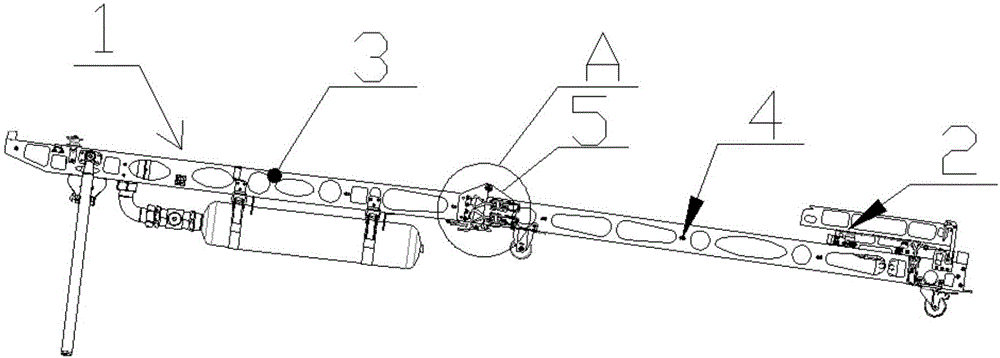
[0047] Such as Figure 6 As shown, the present embodiment provides a launch system for unmanned aerial vehicle launch, which includes the ejection rack for unmanned aerial vehicle launch described in the above-mentioned embodiment one or two, and the compression device arranged on the ejection rack body 1. The air energy storage tank 14 and the air compressor, the compressed air energy storage tank 14 is respectively connected with the air compressor and the cylinder body, for providing compressed air to the cylinder body.

[0048] In order to facilitate the launch of the unmanned aerial vehicle and improve the automation of the ejection system, a control device and a solenoid valve 15 are added to the system. The air storage tank 14 is connected to the cylinder body through the solenoid valve 15, and the control device controls the line through the solenoid valve 15. Connect with the cylinder body, the air compressor in it can be connected with the air energy storage tank 14 ...


PUM


Abstract

The invention relates to a launching frame and system for launching an unmanned aerial vehicle. The launching frame comprises a launching frame body, a skate frame, a launching rope and a driving device. The skate frame is arranged on the launching frame body and used for bearing and launching the unmanned aerial vehicle. The launching rope is arranged at the launching end of the launching frame body. The skate frame is arranged at the initial end of the launching body and can slide in the extending direction of the launching frame body. A driving device is connected with the skate frame and used for driving the skate frame to move in the extending direction of the launching frame body so that the skate frame can collide with the launching rope to launch the unmanned aerial vehicle. When the unmanned aerial vehicle is launched, the driving device is used for driving the skate frame to linearly move on the launching frame body, and motion of the skate frame does not need to be powered by stretching deformation of an elastic string, so that the launching frame is small in overall size, easy to operate and capable of improving the launching efficiency of the unmanned aerial vehicle.

Description

technical field [0001] The invention relates to the technical field of unmanned aerial vehicle launch, in particular to an ejection frame and an ejection system for unmanned aerial vehicle launch. Background technique [0002] Most of the existing ejection frames for small unmanned aerial vehicles use elastic rope as the energy storage medium, and aluminum alloy is used as the ejection frame. The launch end of the slide frame moves, and when the slide frame touches the ejection rope set at the launch end of the slide frame, the slide frame stops moving due to resistance, and the UAV on the slide frame is ejected instantly to complete the launch. [0003] There are the following problems in this kind of elastic rope ejection frame: first, since the energy storage of the elastic rope is a form of stretch-denatured energy storage, long-term use will cause the aging of the elastic rope, which will affect the elasticity and firmness. At the same time, the temperature environment...

Claims


Application Information

Patent Timeline
IPC IPC(8): B64F1/06
CPCB64F1/06B64U70/70
Inventor 冯力祝景军李志宁
Owner 北京韦加智能科技股份有限公司
Why Eureka
Try Eureka