Drive device of a combing machine

A driving device and combing machine technology, which is applied in the direction of combing machines, mechanical equipment, textiles and papermaking, etc., can solve problems such as shortening service life, and achieve the effect of increasing efficiency and optimal transmission

Inactive Publication Date: 2017-02-22
MASCHINENFABRIK RIETER AG
View PDF0 Cites 0 Cited by
  • Summary
  • Abstract
  • Description
  • Claims
  • Application Information

AI Technical Summary

Problems solved by technology

[0006] The extreme vibratory behavior of the double V-belt leads to a situation, in particular, where the electric motor has to provide more power in order to drive the gearbox unit of the comber, where large changes in elongation act on the double V-belt, thereby significantly shortening its service life

Method used


Image

  • Drive device of a combing machine
  • Drive device of a combing machine
  • Drive device of a combing machine

Examples


Embodiment Construction

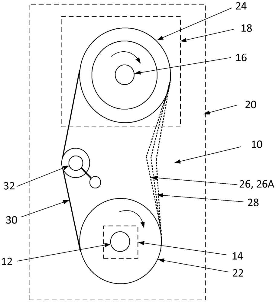
[0026] figure 1 A drive 10 of a known prior art combing machine 20 is shown purely schematically between an electric motor 14 comprising an output shaft 12 and a gearbox 18 comprising an input shaft 16 . To improve the illustration of the interaction of the drive 10 with the electric motor 14, the gearbox unit 18 and the comber 20, these components are described in figure 1 shown in dotted line. The working elements (not shown) of the comber 20 are driven by the gearbox unit 18 .

[0027] The working elements of known combing machines are considered to be, for example, working elements for driving the nipper unit, and / or working elements for driving the detaching rollers, and / or working elements for driving a circular comb.

[0028] A motor pulley 22 is provided on the output shaft 12 of the electric motor 14 , while a gearbox pulley 24 is provided on the input shaft 16 of the gearbox unit 18 . The drive means 26 interacts with the motor pulley 22 and the gearbox pulley 24 ...


PUM

PropertyMeasurementUnit
inertiaaaaaaaaaaa

Abstract

The invention relates to a drive device (10) between a motor having an output shaft (12) and a gear unit having an input shaft (16) a combing machine, and working elements of the combing machine are driven by the drive device. An output shaft (12) of a motor is provided with a motor belt pulley (22), an input shaft (16) of the gear unit is provided with a gear belt pulley (24), and a drive element (26) interacts with the motor belt pulley (22) and the gear belt pulley (24) in an acting force locking manner. According to the drive device, the drive element (26) is designed as a rib V-shaped belt (26B), in particular a multi-wedge belt (26B ').

Description

technical field [0001] The invention relates to a drive device interposed between an electric motor comprising an output shaft of a combing machine and a gearbox unit comprising an input shaft, by means of which driving device the working elements of the combing machine are driven, wherein at the output of the motor A motor pulley is provided on the shaft and a gearbox pulley is provided on the input shaft of the gearbox unit, and wherein the drive member interacts with the motor pulley and the gearbox pulley in a force-locked manner. Background technique [0002] CH-PS 499 635 describes a mechanical drive system for performing intermittent stepping movements at the detaching rollers, reciprocating movements of the nippers of the nipper unit and irregular movements of circular combs on combers. The mechanical drive system includes a gearbox unit with an input shaft driven by an electric motor via a V-belt pulley. In this way, up to 350 nips / minute (nips / min) can be performe...

Claims


Application Information

Patent Timeline
Patent Type & Authority Applications(China)
IPC IPC(8): D01G19/26
CPCD01G19/26F16G5/20
Inventor J.普伦F.弗雷尔C.福斯特
Owner MASCHINENFABRIK RIETER AG
Why Eureka
Try Eureka