Lifting and pulling mechanism of drain valve

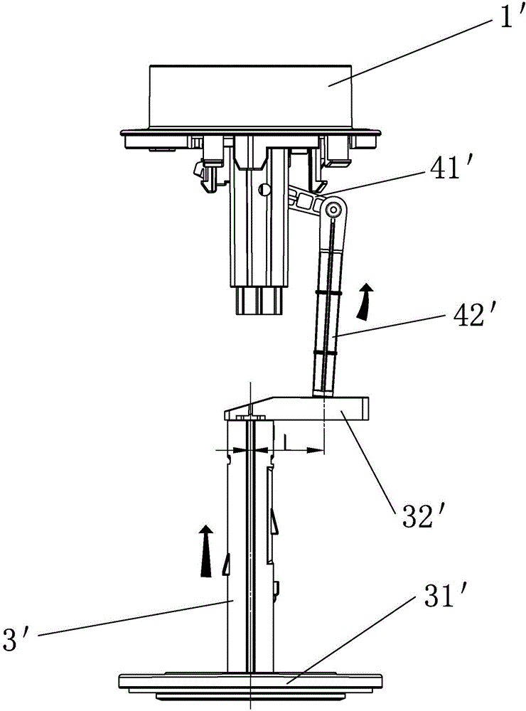
A technology of lifting mechanism and drain valve, which is applied in the field of sanitary ware, can solve problems such as the limitation of lifting position, the inability to shorten the lateral distance at will, and the difficulty in flexibly selecting the lifting position of the riser 3', so as to reduce the opening force value, Effect of Reducing Torsional Moment

Active Publication Date: 2017-02-22
XIAMEN R&T PLUMBING TECH
View PDF3 Cites 1 Cited by
  • Summary
  • Abstract
  • Description
  • Claims
  • Application Information

AI Technical Summary

Problems solved by technology

[0003] In the above-mentioned prior art, the link-type lifting mechanism composed of the pressing rod 41' and the connecting rod 42' ensures that the lifting tube 3' can be pulled smoothly, and the lifting position of the lifting tube 3' reaches the position of the lifting tube. The horizontal distance of 3' needs to have a certain length, and the horizontal distance cannot be shortened arbitrarily, so it is difficult to flexibly select the lifting position of the riser 3' according to the needs, and the lifting position is limited

Method used


Image

  • Lifting and pulling mechanism of drain valve
  • Lifting and pulling mechanism of drain valve
  • Lifting and pulling mechanism of drain valve

Examples


Embodiment Construction

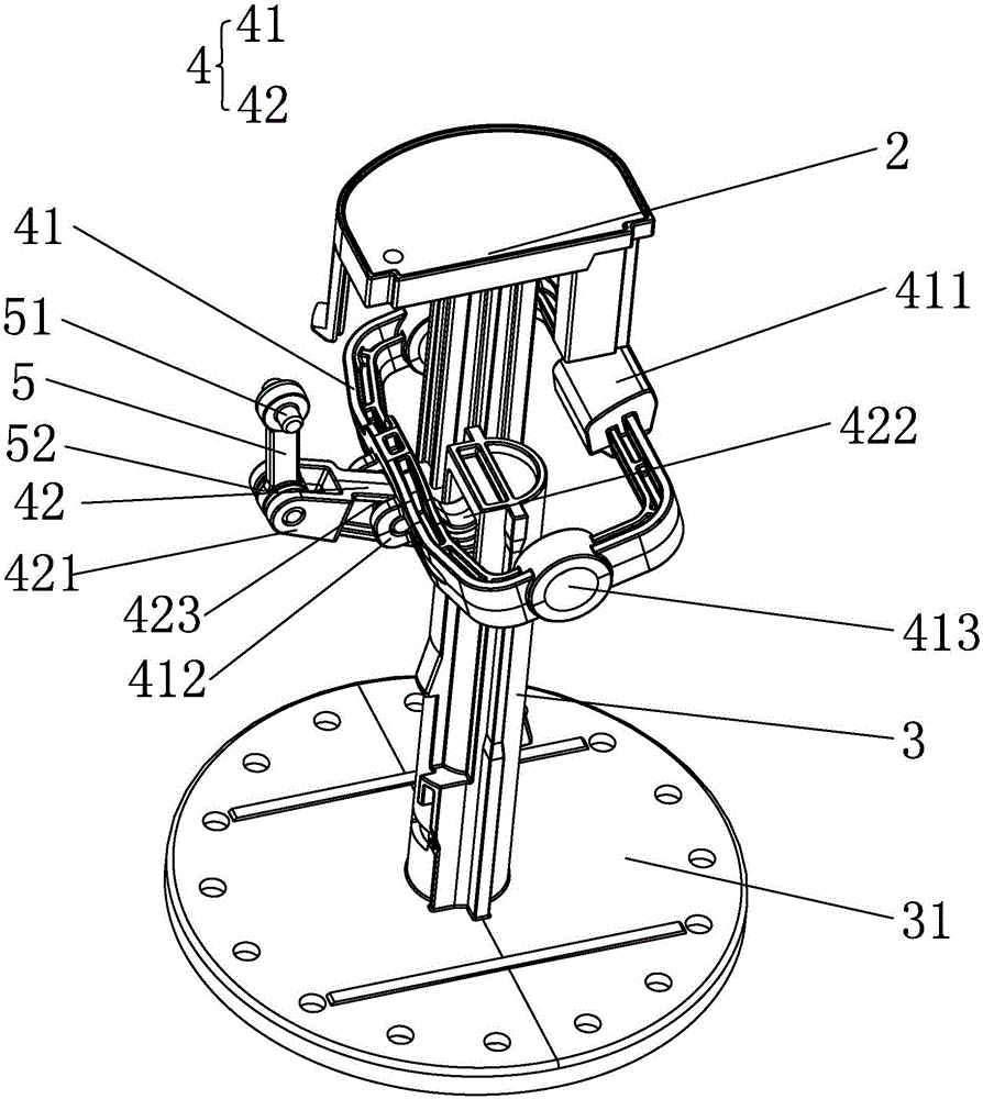
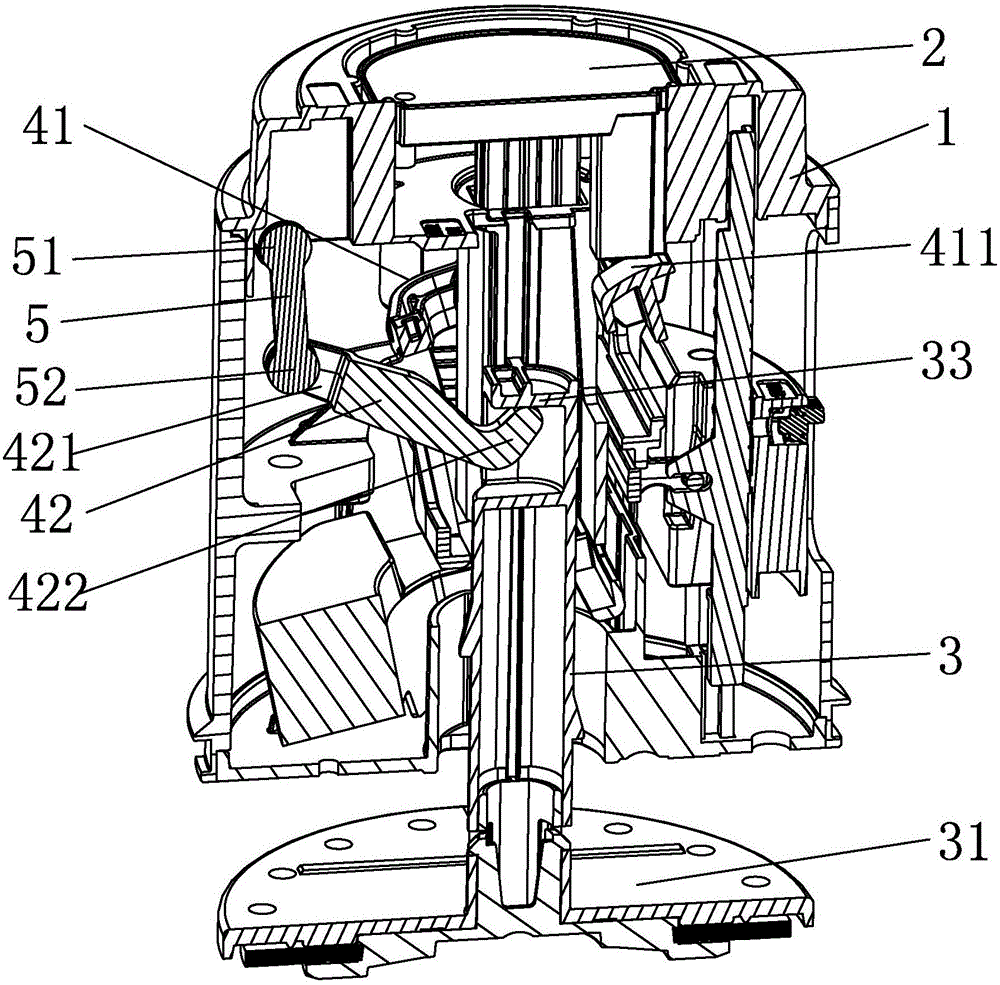
[0027] Such as Figure 2 to Figure 4 , Figure 2 to Figure 4 A lifting mechanism 4 of a drain valve according to the first embodiment of the present invention is shown. The drain valve includes a valve body 1, an activation element 2, a riser 3 and a lifting mechanism 4. The lifting mechanism 4 is arranged on the valve of the drain valve. In the body 1, it is used to drive and cooperate with the actuating element 2 of the drain valve to pull the lift pipe 3 installed in the valve body 1. The actuating element 2 in this embodiment is a button, and the button is movably installed on the top of the valve body 1 In the provided button seat, the bottom end of the riser 3 is fixedly connected with a valve disc 31 that matches the drain port of the drain valve, and the starting element 2 lifts the riser 3 upwards through the lifting mechanism 4 to drive the valve disc 31 to move upwards. And open the drain port of the drain valve to realize draining. The pulling mechanism 4 at leas...


PUM


Abstract

The invention discloses a lifting and pulling mechanism of a drain valve. The lifting and pulling mechanism of the drain valve is arranged in a valve body of the drain valve and is used for performing transmission cooperation with a starting component of the drain valve to lift and pull a lifting pipe which is movably arranged in the valve body and is fixedly connected with a valve disk cooperating with a drainage port of the drain valve. The lifting and pulling mechanism of the drain valve is characterized by at least comprising a connecting rod I and a connecting rod II, wherein the connecting rod I is pivoted to the valve body and is in transmission cooperation with the starting component; one end of the connecting rod I is pivoted to a part between the first end and the second end of the connecting rod II; while the connecting rod II is pulled by the connecting rod to rotate around the first end of the connecting rod II, the first end of the connecting rod II forms abdicating displacement relative to the valve body and the second end of the connecting rod pulls the lifting pipe. The lifting and pulling mechanism can select the lifting and pulling position of the lifting pipe flexibly according to requirements on the premise of guaranteeing smooth lifting and pulling of the lifting pipe so as to reduce the torsional moment when the lifting pipe is lifted by selecting the optimal lifting and pulling position, reduce the starting force value of the drain valve and achieve the labor-saving effect.

Description

technical field [0001] The invention relates to the field of sanitary ware, in particular to a lifting mechanism for a drain valve. Background technique [0002] The lifting mechanism of the existing drain valve generally includes a button, a pressing rod 41', a connecting rod 42', a lifting arm 32', and a lifting pipe 3', such as figure 1 As shown, press the button, press the button to press down one end of the pressure rod 41', the other end of the pressure rod 41' lifts up and pulls the connecting rod 42' to move upward, and the connecting rod 42' pulls the lifting tube through the horizontally arranged lifting arm 34' 3' move upwards together, the riser 3' guides and cooperates with the valve body 1' and drives the valve disc 31' to move upwards to open the drain port of the drain valve to realize the draining process. [0003] In the above-mentioned prior art, the link-type lifting mechanism composed of the pressing rod 41' and the connecting rod 42' ensures that the l...

Claims


Application Information

Patent Timeline
Patent Type & Authority Applications(China)
IPC IPC(8): E03D5/09
CPCE03D5/09
Inventor 王志忠王兴东蒋友平周洪文
Owner XIAMEN R&T PLUMBING TECH
Why Eureka
Try Eureka