A kind of injection intelligent dispensing device
A technology of dispenser and rotary injection, which is applied in wellbore/well components, production fluids, earth-moving drilling, etc. Advanced problems, to achieve the effect of long effective working life
- Summary
- Abstract
- Description
- Claims
- Application Information
AI Technical Summary
Problems solved by technology
Method used
Image


Examples
Embodiment 1
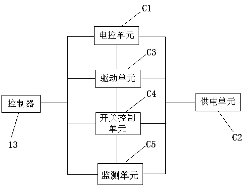
[0026] Such as figure 1 and figure 2 As shown, the present invention provides a wheel injection intelligent dispenser, including a dispenser connected in series on the oil pipe, an adjustment cavity 3 is set on the outer side of the center pipe 4 in the dispenser, and the lower part of the adjustment cavity 3 is provided with an opening , the opening is equipped with a regulating valve 12, and it is characterized in that: a control module for controlling the opening and closing of the regulating valve 12 is also installed in the housing of the dispenser, and the control module is also electrically connected with the ground controller 13, and the control module It also includes at least one reader capable of identifying electronic tags.
[0027] Such as figure 1 As shown, the control module includes an electrically connected electric control unit C1, a power supply unit C2, a drive unit C3, a switch control unit C4 and a monitoring unit C5, and the electric control unit C1, ...
Embodiment 2
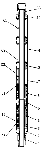
[0033] On the basis of Example 1, such as figure 2 As shown, the interior of the dispenser is a hollow water injection channel, and water is injected into the water injection channel of the dispenser from the oil pipe. The opening of the lower part is injected into each stratum, and the outside of the dispenser includes an upper joint body 11, a connecting body 5, a central pipe 4, and a lower joint body 1, which are sequentially connected from top to bottom. Shell one 9, shell two 7, shell three 6 are arranged.
[0034] The electric control unit C1 and the power supply unit C2 are arranged in the housing one 9, and the electric control unit C1 and the power supply unit C2 are connected by a connecting piece 8, which is used as a transition connection to facilitate the arrangement of the circuits of each unit. .
[0035] The driving unit C3 is set in the second casing 7 , the switch control unit C4 is set in the third casing 6 , and the monitoring unit C5 is set in the adju...
Embodiment 3
[0037] On the basis of Example 2, such as figure 2 As shown, further, in order to seal the shell one 9, the upper end of the shell one 9 is provided with an upper end cap 10 . In order to seal the adjustment cavity 3 , a lower end cap 2 is provided at the lower end of the adjustment cavity 3 .
[0038] The lower end cap 2 and the adjustment cavity 3, the adjustment cavity 3 and the upper layer of the connecting body 5, the connecting body 5 and the shell three 6, the shell three 6 and the shell two 7, the shell two 7 and the transition piece 8, the transition Part 8 and shell one 9, shell one 9 and upper end cap 10, upper end cap 10 and upper joint body 11 are all connected by plugging.
[0039] The lower end cap 2 and the adjustment cavity 3, the adjustment cavity 3 and the connecting body 5, the connecting body 5 and the shell three 6, the shell three 6 and the shell two 7, the shell two 7 and the transition piece 8, the transition piece 8 and shell one 9, between shell o...
PUM
 Abstract
Description
Claims
Application Information