
Rotor assembly, solenoid valve, ir-cut switch and iris aperture

A rotor and component technology, applied in the field of IR-CUT switch, IRIS aperture drive device, and solenoid valve, can solve the problems of small pull-out force, poor workability, low pull-out force stability, etc., to increase the rotation pull-out force, Improve stability, good anti-fool effect

Active Publication Date: 2018-09-28
东莞市维斗科技股份有限公司
View PDF6 Cites 0 Cited by
  • Summary
  • Abstract
  • Description
  • Claims
  • Application Information

AI Technical Summary

Problems solved by technology

In the prior art, the rocker and the permanent magnet are fixedly connected by bonding process, resulting in the following disadvantages: 1) The assembly process is complicated, the efficiency is low, the workability is poor, and the automation cost is high (difficult dispensing operation, efficiency low, easy to leave glue, more glue, less glue); 2) dispensing control pull-off force, poor control of glue volume, small pull-off force, low pull-off force stability, and poor consistency; 3) Assembly between permanent magnet and rocker Low precision, the N pole and S pole of the permanent magnet are on the circumference, which cannot be marked, and the assembly precision is low

Method used


Image

  • Rotor assembly, solenoid valve, ir-cut switch and iris aperture
  • Rotor assembly, solenoid valve, ir-cut switch and iris aperture
  • Rotor assembly, solenoid valve, ir-cut switch and iris aperture

Examples


Embodiment Construction

[0018] The technical solutions in the embodiments of the present invention are clearly and completely described below in conjunction with the accompanying drawings in the embodiments of the present invention. Obviously, the described embodiments are only part of the embodiments of the present invention, not all of them. Based on the embodiments of the present invention, all other embodiments obtained by persons of ordinary skill in the art without making creative efforts belong to the protection scope of the present invention.

[0019] In the following description, a lot of specific details are set forth in order to fully understand the present invention, but the present invention can also be implemented in other ways different from those described here, and those skilled in the art can do it without departing from the meaning of the present invention. By analogy, the present invention is therefore not limited to the specific examples disclosed below.

[0020] Such as Figure...


PUM


Abstract

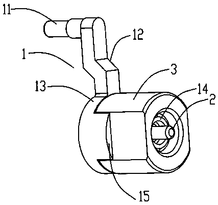
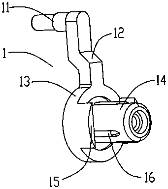
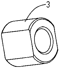
The invention discloses a rotor component, an electromagnetic valve, an IR-CUT switcher and an IRIS aperture, and relates to the technical field of electromagnets, IR-CUT switchers and IRIS aperture driving devices. The rotor component comprises a crank, a shaft core and a permanent magnet, wherein the shaft core is fixed on the crank or passes through the crank and is fixedly connected with a device outside the rotor component; a block is arranged on the crank and is coaxial to the shaft core; the permanent magnet has an annular structure; two planes are arranged on the outer side wall of the permanent magnet and are relatively parallel; and when the permanent magnet is arranged on the crank in a sleeving manner, the plane on the side wall of the permanent magnet is in direct contact with the plane on the inner wall of the permanent magnet. According to the rotor component, a dispensing process between the permanent magnet and the crank can be reduced, fool-proofing spacing is carried out for the permanent magnet structurally, the magnetic poles of the permanent magnet are marked, and the rotation pulling force between the crank and the permanent magnet is large. The rotor component has the advantages of high stability, high uniformity, high accuracy, simple process, high efficiency, good operability and excellent automation.

Description

technical field [0001] The invention relates to the technical field of a solenoid valve, an IR-CUT switcher and an IRIS aperture driving device, in particular to a rotor assembly and a solenoid valve using the rotor assembly, an IR-CUT switcher and an IRIS aperture. Background technique [0002] In the prior art, whether it is a solenoid valve, an IR-CUT switch or an IRIS aperture, a rotor will be used. The rotor used in the above devices generally includes a crank handle, a shaft core and a permanent magnet. The shaft core is fixed on the crank handle or worn The crank handle is fixedly connected with components other than the rotor assembly, and the permanent magnet is sleeved on the rock handle. In the prior art, the rocker and the permanent magnet are fixedly connected through the bonding process, resulting in the following disadvantages: 1) The assembly process is complicated, the efficiency is low, the workability is poor, and the automation cost is high (difficult dis...

Claims


Application Information

Patent Timeline
Patent Type & Authority Patents(China)
IPC IPC(8): F16K31/08F16K31/11G02B26/04H01F7/02
CPCF16K31/08F16K31/10G02B26/008G02B26/04H01F7/0221
Inventor 钟木生杨俊文赵少伟
Owner 东莞市维斗科技股份有限公司
Learn More