Remote fluorescent LED (Light Emitting Diode) device

A technology of LED devices and remote fluorescence, applied in lighting devices, lighting device components, light sources, etc., can solve the problems of low work efficiency, unacceptable, rising costs, etc., achieve high production efficiency and product qualification rate, reduce equipment cost, the effect of prolonging the service life

Inactive Publication Date: 2014-02-05
SOUTH CHINA NORMAL UNIVERSITY
View PDF9 Cites 15 Cited by
  • Summary
  • Abstract
  • Description
  • Claims
  • Application Information

AI Technical Summary

Problems solved by technology

This method has many disadvantages: for example, the phosphor powder is easy to precipitate, and it is unevenly dispersed in the adhesive, resulting in poor light emitting performance of the LED, and problems such as color spots and color deviation.
At the same time, most manufacturers use artificial dot phosphor, which has low work efficiency and is difficult to guarantee the consistency of products.
In addition, due to the close contact between the phosphor powder and the LED chip, the high temperature generated by the LED operation is not conducive to the stability of the crystal structure of the phosphor powder, which will significantly shorten the service life of the LED while affecting the light output performance.
[0004] On the other hand, in the remote fluorescent LEDs proposed in the past, the lampshade is directly made by mixing the phosphor powder with the light-transmitting resin, or the fluorescent resin is pressed into a film and bonded to the light-transmitting resin lampshade, so that the phosphor powder is distributed from the original The small area on the chip is increased to the entire lampshade, which greatly increases the amount of phosphor used, resulting in a sharp rise in cost. At the same time, because the fluorescent lampshade shows the color of phosphor powder when the LED chip is not working, it is not beautiful, so it is not easy to be accepted by the market.

Method used


Image

  • Remote fluorescent LED (Light Emitting Diode) device
  • Remote fluorescent LED (Light Emitting Diode) device
  • Remote fluorescent LED (Light Emitting Diode) device

Examples


Embodiment 1

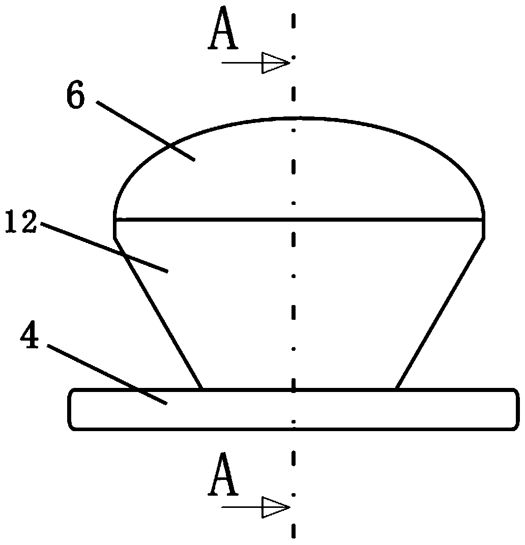
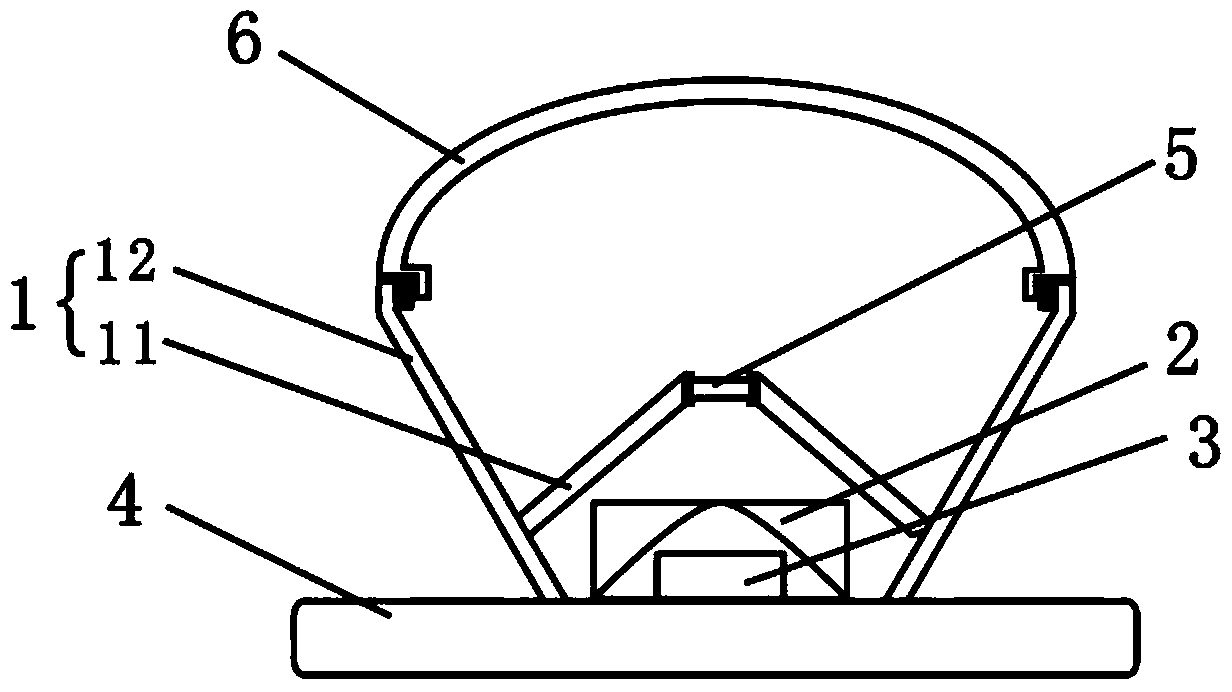
[0048] Rare earth fluorescent resin sheet 5 thickness: 2.3mm, radius 10.8mm; phosphor concentration: 4%; phosphor type: YAG yellow powder; distance between LED chip 3 and rare earth fluorescent resin sheet 5: 0.8cm; distance between light diffusion lampshade 6 and rare earth fluorescent Resin sheet 5 distance: 0.5cm; white paper thickness 0.1mm; white LED: 3W positive white light.

[0049]

[0050]

Embodiment 2

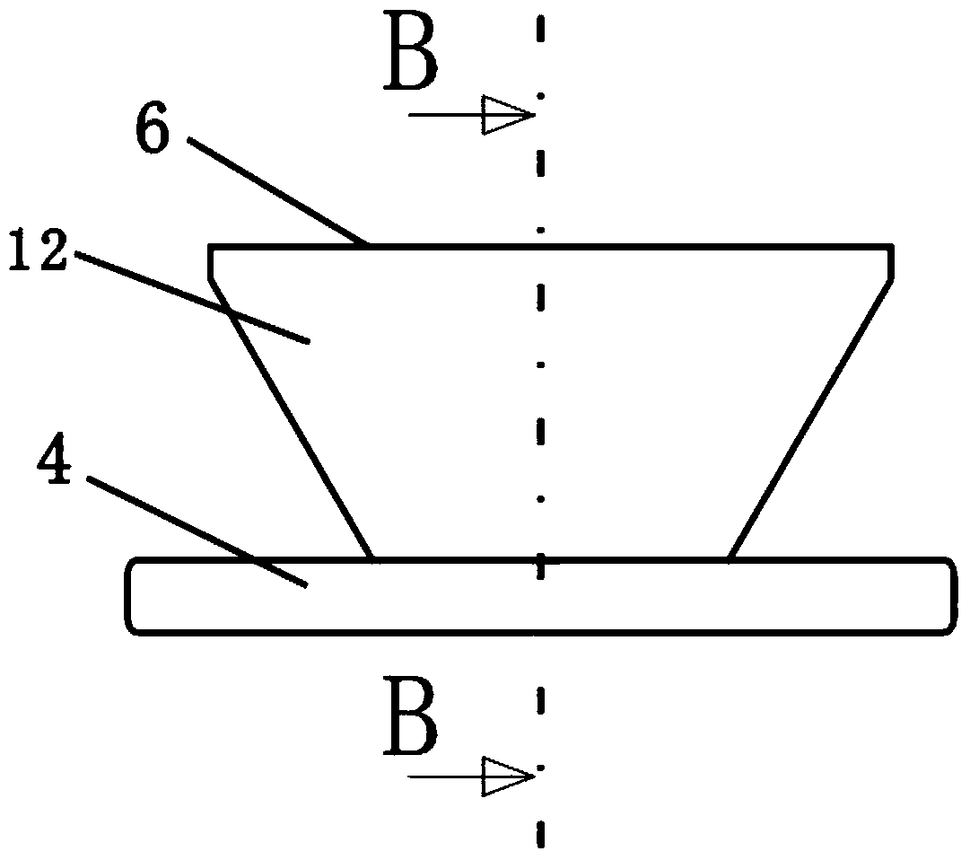
[0052] Rare earth fluorescent resin sheet 5 thickness: 3.0mm, radius 8mm; fluorescent powder concentration: 4%; phosphor powder type: green powder + red powder; distance between LED chip 3 and rare earth fluorescent resin sheet 5: 2cm; distance between light diffusion lampshade 6 and rare earth fluorescent resin Sheet 5 distance: 4.5cm; white paper thickness 0.1mm; white LED: 3W warm white light.

[0053]

[0054] The data from the two examples show that the combination of the blue LED chip and the 30° lens has the best effect.


PUM


Abstract

The invention discloses a remote fluorescent LED (Light Emitting Diode) device which comprises a light diffusion lampshade, a rare-earth fluorescent resin sheet, an LED condensing lens, an LED chip and a combined reflection cup, wherein the combined reflection cup comprises an outer reflection cup and an inner reflection cup; the inner reflection cup is upside-down and is combined with the outer reflection cup; a first sealed space is formed after the opening of the bottom of the inner reflection cup is combined with the rare-earth fluorescent resin sheet; the LED condensing lens and the LED chip are located in the first sealed space; the LED chip is located below the LED condensing lens and above the outer reflection cup; the outer reflection cup and the light diffusion lampshade are tightly connected to form a second sealed space; the first sealed space is located in the second sealed space. Fluorescent powder is separated from the LED chip to be conductive to heat radiation of the chip and keep use stability of the fluorescent powder; a light conversion range is limited in a small region, so that use amount of the fluorescent resin sheet is reduced, and cost is lowered; the light diffusion lampshade protects the inner part, so that the lights are soft and the appearance is beautiful.

Description

technical field [0001] The invention relates to a white light LED light source device in the lighting field, in particular to a remote fluorescent LED device. Background technique [0002] Since the breakthrough of blue LED in 1994, the three-primary color light-emitting system composed of red LED, green LED and blue LED has been completed, laying the foundation for the realization of white LED. Compared with traditional incandescent lamps and fluorescent lamps, white LEDs have many advantages: long service life, high efficiency and energy saving, fast luminous response, small size, solidification, good shock resistance, etc., and are known as green energy in the 21st century. [0003] At present, the preparation of white LED mainly uses the phosphor powder coating LED light conversion method. The method is to disperse the phosphor powder in the adhesive (usually epoxy resin adhesive), and then point it to the surface of the LED chip. This method has many disadvantages: fo...

Claims


Application Information

Patent Timeline
Patent Type & Authority Applications(China)
IPC IPC(8): F21S2/00F21V3/04F21V13/00F21Y101/02F21K9/20F21Y115/10
Inventor 石光王泽忠侯琼
Owner SOUTH CHINA NORMAL UNIVERSITY
Why Eureka
Try Eureka