Supercharge Your Innovation With Domain-Expert AI Agents!

Supporting mounting rack

A mounting frame and mounting plate technology, applied in the field of machinery, can solve the problems of reduced motor resource utilization, waste of resources and space, and large space occupation, and achieve the effects of saving storage, flexible and convenient use, and avoiding waste of resources.

Inactive Publication Date: 2017-02-22
张世友
View PDF6 Cites 0 Cited by
  • Summary
  • Abstract
  • Description
  • Claims
  • Application Information

AI Technical Summary

Problems solved by technology

[0002] In real life, there are many small machines that are not commonly used, such as pulverizers, pulverizers, etc., which need the power of the motor to work. When you often buy these machines, you need to buy a matching motor, which not only reduces the utilization of motor resources, but also If the motor is not used for a long time, it will easily lead to damage, and it will also increase the space occupied by these infrequently used machines, resulting in a waste of resources and space

Method used


Image

  • Supporting mounting rack
  • Supporting mounting rack
  • Supporting mounting rack

Examples


Embodiment 1

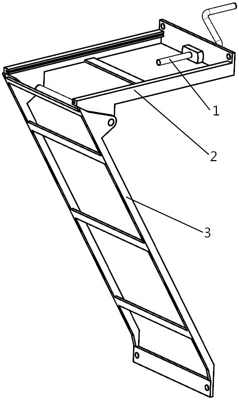
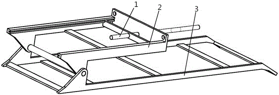
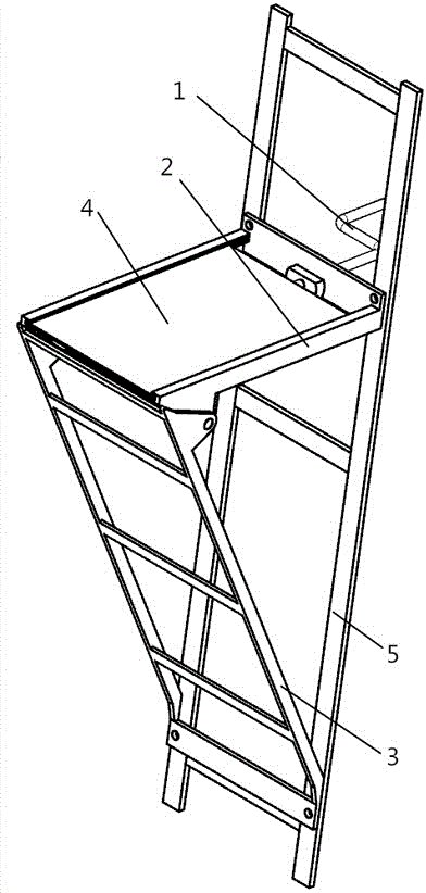
[0028] see Figure 1 to Figure 6 , the supporting mounting frame of the present invention includes a mounting plate 4, a horizontal frame 2 for fixing the mounting plate 4, an inclined frame 3 for supporting the horizontal frame 2, and a curved bar 1 for locking the mounting plate 4; the horizontal frame 2 One end is connected with one end of the inclined frame 3, and the other end of the horizontal frame 2 and the inclined frame 3 are connected with the rice mill frame 5; the horizontal frame 2 includes a horizontal frame side bar I21a, a horizontal frame side bar II21b, and a horizontal frame end plate 24, There are concave rails 20 inside the side bars of the two horizontal frames, and the two sides of the mounting plate 4 are slidingly assembled in the concave rails 20; the side of the horizontal frame end plate 24 of the horizontal frame 2 is provided with a screw-in device for the curved rod 1, and the curved rod 1 is formed by a The Z-shaped three-segment curved rod for...

Embodiment 2

[0038] see Figure 7 , the screw-in device is composed of a horizontal frame end plate 24 and a horizontal frame baffle plate 28. The frame baffle plate 28 is respectively provided with a through hole I27 and a through hole II29 on the same axis, and at least one of the two through holes is a threaded hole matched with the thread of the curved rod 1, otherwise it is consistent with the embodiment 1.


PUM


Abstract

The invention discloses a supporting mounting rack. The supporting mounting rack is characterized in that a mounting plate (4), a transverse frame (2) used for fixing the mounting plate (4), an inclined frame (3) used for supporting the transverse frame (2) and a cranked lever (1) used for locking the mounting plate (4) are included; one end of the transverse frame (2) is connected with one end of the inclined frame (3), and the other end of the transverse frame (2) and the other end of the inclined frame (3) are both connected with an outside entity (5); the transverse frame (2) comprises a transverse frame side rod I (21a), a transverse frame side rod II (21b) and a transverse frame end plate (24), concave rails (20) are arranged on the inner sides of the two transverse frame side rods, the two sides of the mounting plate (4) are slidably assembled in the concave rails (20), a screwing device of the cranked lever (1) is arranged on one side of the transverse frame end plate (24) of the transverse frame (2), and one end of the cranked lever (1) is screwed out of the screwing device to exactly abut against the mounting plate (4). According to the supporting mounting rack, a small machine can conveniently use motors of other machines, and the supporting mounting rack is detachable and small in occupied space and saves resources and space.

Description

technical field [0001] The invention belongs to the field of machinery, and in particular relates to a support installation frame which is convenient for disassembly and storage. Background technique [0002] In real life, there are many small machines that are not commonly used, such as pulverizers, pulverizers, etc., which need the power of the motor to work. When you often buy these machines, you need to buy a matching motor, which not only reduces the utilization of motor resources, but also If the motor is not used for a long time, it will easily lead to damage, and it will also increase the space occupied by these infrequently used machines, resulting in a waste of resources and space. Contents of the invention [0003] The object of the present invention is to overcome the above disadvantages and provide a support installation frame that can facilitate the use of motors of other machines by small machines, is detachable, takes up little space, and saves resource...

Claims


Application Information

Patent Timeline
Patent Type & Authority Applications(China)
IPC IPC(8): F16M13/02
CPCF16M13/022
Inventor 张世友
Owner 张世友
Features
  • R&D
  • Intellectual Property
  • Life Sciences
  • Materials
  • Tech Scout
  • Unparalleled Data Quality
  • Higher Quality Content
  • 60% Fewer Hallucinations
Learn More