
Gas tank management system

A management system and a gas tank technology, applied in the field of gas tank management systems, can solve the problems of overdue use of the gas tank, the inability of ordinary users to accurately grasp the service life of the gas tank, and the inability to calculate the number of times the gas tank is inflated and the gas consumption of the user, so as to ensure safety. Effect

Active Publication Date: 2017-02-22
深圳市放大科技有限公司
View PDF10 Cites 1 Cited by
  • Summary
  • Abstract
  • Description
  • Claims
  • Application Information

AI Technical Summary

Problems solved by technology

The gas tank in the prior art is composed of a tank body and an ordinary valve installed at the gas outlet of the tank body. This gas tank with a simple structure does not have an intelligent monitoring function, and cannot monitor the remaining gas content in the gas tank. The user finds that the gas tank cannot be ignited normally during use, so that he can judge that the gas tank has been used up, which causes a lot of inconvenience to the user
In addition, this kind of gas tank in the prior art has low safety, and common users cannot accurately grasp important data such as the service life of the gas tank, and cannot determine when the gas tank should be replaced, resulting in the use of gas tanks beyond the expiration date, and the existence of gas tanks with overdue service Potential safety hazards; it is also impossible to calculate the gas tank filling times, the user's gas consumption and other data, causing confusion and inconvenience in management for gas tank providers and ordinary users

Method used


Image

  • Gas tank management system
  • Gas tank management system
  • Gas tank management system

Examples


Embodiment Construction

[0021] The following examples are used to illustrate the present invention, but are not intended to limit the scope of the present invention.

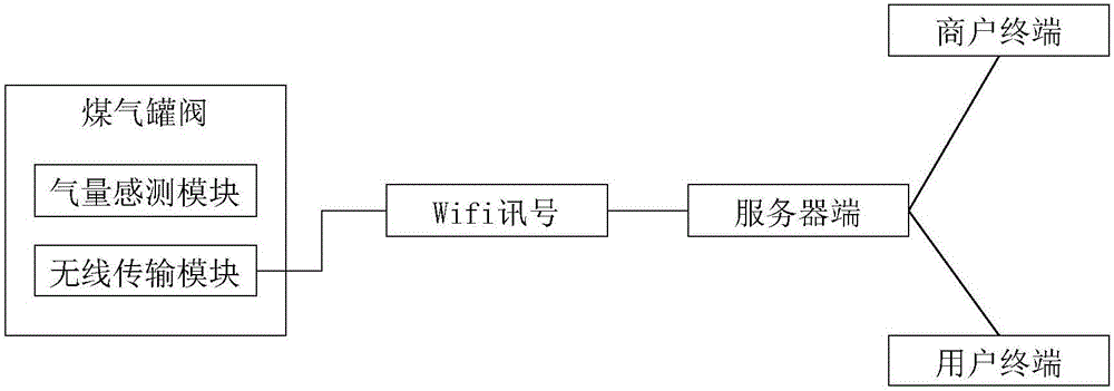
[0022] Such as figure 1 As shown, it is the first embodiment proposed by the present invention. The gas tank management system of the present invention includes a gas tank valve and a server end. The gas tank valve includes a wireless transmission module and a gas volume sensing module. The gas volume sensing module is used for To detect the gas storage in the gas tank, the gas volume sensing module can be an air pressure sensor, which uses air pressure to sense the gas storage in the gas tank, the gas volume sensing module is connected to the wireless transmission module, and the wireless transmission module senses the gas volume The gas storage in the gas tank detected by the module is transmitted to the server. The transmission method can be transmitted to the server through wifi or through a data network of a mobile terminal. In th...


PUM


Abstract

The invention discloses a gas tank management system. The system comprises a gas tank valve and a server end. The gas tank valve comprises a wireless transmission module and a gas amount sensing and measuring module. The gas amount sensing and measuring module is use for sensing and measuring the amount of remaining gas in a gas tank and connected with the wireless transmission module. The amount of the remaining gas in the gas tank sensed and measured by the gas amount sensing and measuring module is transmitted to the server end through the wireless transmission module. The system further comprises a user terminal and a commercial tenant terminal. The user terminal and the commercial tenant terminal both can be connected to the server end to obtain the amount of the remaining gas in the gas tank so that the using condition of the gas tank can be leant about at any moment. In addition, the server end can further comprise a charging module, a gas tank use record module, a user use record module, a monitoring module and the like, and the gas tank can be used more conveniently and safely.

Description

technical field [0001] The invention relates to the technical field of intelligent monitoring, in particular to a gas tank management system. Background technique [0002] In the prior art, a gas tank is a widely used gas storage device. The gas tank in the prior art consists of a tank body and an ordinary valve installed at the gas outlet of the tank body. This gas tank with a simple structure does not have an intelligent monitoring function, and cannot monitor the remaining gas content in the gas tank. The user finds that the gas tank cannot be ignited normally in the process of use, and can judge that the gas tank has been used up, which causes a lot of inconvenience to the user. In addition, this kind of gas tank in the prior art has low safety, and common users cannot accurately grasp important data such as the service life of the gas tank, and cannot determine when the gas tank should be replaced, resulting in the use of the gas tank beyond the expiration date, and th...

Claims


Application Information

Patent Timeline
Patent Type & Authority Applications(China)
IPC IPC(8): F17C1/00F17C13/02
CPCF17C1/00F17C13/028F17C2250/0605
Inventor 赵磊
Owner 深圳市放大科技有限公司
Learn More