A field straw burning grain drying device

A drying device and straw technology, applied in the directions of drying, drying machine, heating device, etc., can solve problems such as troublesome, large coal power consumption, etc., achieve convenient use, save coal power consumption, and ensure sufficiency. Effect

Active Publication Date: 2018-10-26
GUANGXI UNIV
View PDF10 Cites 0 Cited by
  • Summary
  • Abstract
  • Description
  • Claims
  • Application Information

AI Technical Summary

Problems solved by technology

[0002] After harvesting, grain often contains a lot of water. For the convenience of transportation and storage, grain needs to be dried before stacking. The existing heat sources of grain dryers mainly include coal and electricity, and there are also a small amount of them. Waste fuels such as straw are burned. However, due to the large grain output today, for some coal-fired dryers, the drying often requires a large amount of coal-fired energy, and the burning of straw requires harvesting and transporting the straw to the dryer. It is very troublesome to carry out burning everywhere; as we all know, after the grain is harvested, there will be a large amount of straw left in the farmland, and the amount of straw is directly proportional to the harvested amount of grain. In many places, direct combustion is used to remove straw, and burning straw If the heat can be directly used in grain harvesting, it will not only avoid the trouble of transferring to the dryer, but also effectively use the heat of straw burning, killing two birds with one stone. Therefore, the applicant designed a kind of machine that can effectively use the heat of straw burning in the field Dryer

Method used


Image

  • A field straw burning grain drying device
  • A field straw burning grain drying device
  • A field straw burning grain drying device

Examples


Embodiment Construction

[0013] The technical solution of this patent will be further described in detail below in conjunction with specific embodiments.

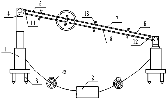
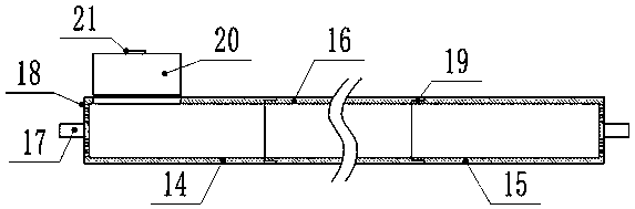
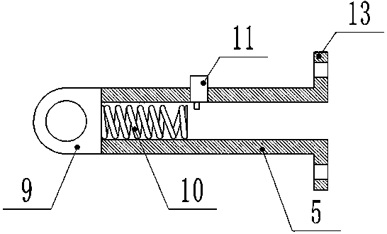
[0014] see Figure 1-4 , a field straw burning grain drying device, comprising an electric telescopic rod 1, a sliding frame, a drying cylinder and a control box 2, the electric telescopic rod 1 is provided with four, placed in the four corners of the field when in use, electric The lower end of the telescopic rod 1 is threadedly connected with a ground bolt 3. When it is convenient to drill the ground, the stability is improved through the ground bolt 3. If it is inconvenient to drill the ground, the electric telescopic rod 1 can be disassembled to facilitate the placement of the electric telescopic rod 1. The upper end of the electric telescopic rod 1 is fixedly connected with a The turret 4 is rotatably connected to the turret 4, and the drying cylinder is rotatably connected to the turret; the sled is composed of a head frame 5, a tail frame 6,...


PUM


Abstract

The invention discloses a field straw combusting and grain drying device. The device comprises electric telescopic rods, a sliding frame, a drying cylinder and a control box; the lower ends of the electric telescopic rods are in threaded connection with ground bolts, the upper ends of the electric telescopic rods are fixedly connected with rotating frames, the sliding frame is rotatably connected to the rotating frames, the drying cylinder is rotatably connected to the sliding frame, the sliding frame and the drying cylinder are both of threaded dismounting and mounting structures, a plurality of air exhaust holes are formed in the drying cylinder, a cylinder door is hinged to one side of the wall of the drying cylinder, and a clamping buckle is arranged on the cylinder door; a controller and a storage battery are arranged in the control box. Straw does not need to be cut and transported, heat of field straw combusting is fully used for carrying out grain drying, the electric coal energy consumption of grain drying is saved, after the grain is harvested, the grain can be directly dried locally, the transport flow of transferring and drying is omitted, operation is more convenient, meanwhile, after drying, the weight is reduced, and transportation is more labor-saving, due to a dismounting and mounting type structure, splicing and dismounting are convenient, the device is suitable for being used by farmlands with the different lengths and widths, the structure is simple, and use and transportation are convenient.

Description

technical field [0001] The invention relates to an agricultural equipment, in particular to a field straw burning grain drying device. Background technique [0002] After harvesting, grain often contains a lot of water. For the convenience of transportation and storage, grain needs to be dried before stacking. The existing heat sources of grain dryers mainly include coal and electricity, and there are also a small amount of them. Waste fuels such as straw are burned. However, due to the large grain output today, for some coal-fired dryers, the drying often requires a large amount of coal-fired energy, and the burning of straw requires harvesting and transporting the straw to the dryer. It is very troublesome to carry out burning everywhere; as we all know, after the grain is harvested, there will be a large amount of straw left in the farmland, and the amount of straw is directly proportional to the harvested amount of grain. In many places, direct combustion is used to remo...

Claims


Application Information

Patent Timeline
Patent Type & Authority Patents(China)
IPC IPC(8): F26B11/04F26B25/04F26B23/02F26B25/16F26B25/00
CPCF26B11/0463F26B23/028F26B25/00F26B25/04F26B25/16F26B2200/06
Inventor 周源思
Owner GUANGXI UNIV
Why Eureka
Try Eureka