A 3D machine vision space detection and calibration method
A technology of machine vision and calibration method, which is applied in photogrammetry/video metrology, instruments, measuring devices, etc. It can solve the problems of relative positioning detection without public information, and achieve good accuracy.
- Summary
- Abstract
- Description
- Claims
- Application Information
AI Technical Summary
Problems solved by technology
Method used
Image
Examples
Embodiment Construction
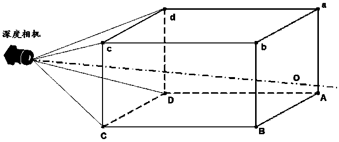
[0023] A 3D machine vision space detection and calibration method uses nine spatial feature points for space calibration. Such as figure 1 As shown, the nine feature points are: the four vertices A, B, b, and a that constitute the surface ABba directly in front of the depth camera and passing through the camera axis; the intersection point O between the depth camera axis and the surface ABba; parallel to the surface ABba The four vertices D, C, c, and d of the surface DCcd of the depth camera; the angle between the axis of the depth camera and the surface ABba is α.
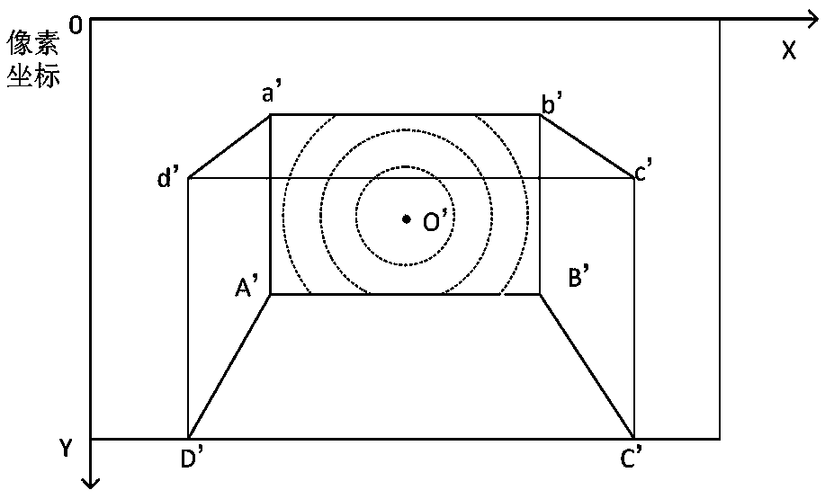
[0024] Such as figure 2 As shown, the mapping of the above nine feature points in the depth camera pixel coordinate OXY image is: A', B', C', D', O', a', b', c', d', where O ' is the center point of the image. The surface ABba is mapped to the surface A'B'b'a'; the surface DCcd is mapped to the D'C'c'd'; the line AD is mapped to the line A'D', the line BC is mapped to the line B'C', and the line ad is mapped ...
PUM
 Abstract
Description
Claims
Application Information
 - R&D
- Intellectual Property
- Life Sciences
- Materials
- Tech Scout
- Unparalleled Data Quality
- Higher Quality Content
- 60% Fewer Hallucinations
Browse by: Latest US Patents, China's latest patents, Technical Efficacy Thesaurus, Application Domain, Technology Topic, Popular Technical Reports.
© 2025 PatSnap. All rights reserved.Legal|Privacy policy|Modern Slavery Act Transparency Statement|Sitemap|About US| Contact US: help@patsnap.com


