
3D machine vision space detection calibration method

A machine vision and calibration method technology, applied in photogrammetry/video surveying, instruments, measuring devices, etc., can solve the problem of relative positioning detection without public information, etc., and achieve the effect of good accuracy

Active Publication Date: 2017-02-22
SHANGHAI JIQING HUISHI TECH CO LTD
View PDF10 Cites 8 Cited by
  • Summary
  • Abstract
  • Description
  • Claims
  • Application Information

AI Technical Summary

Problems solved by technology

Relative positioning detection and calibration for dynamic space has not yet seen relevant public information

Method used


Image

  • 3D machine vision space detection calibration method
  • 3D machine vision space detection calibration method
  • 3D machine vision space detection calibration method

Examples


Embodiment Construction

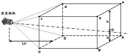
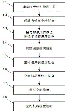
[0023] A 3D machine vision space detection and calibration method, such as image 3 As shown, its specific implementation steps are as follows:

[0024] (1) Determine the depth camera detection station (3.1), so that the spatial detection area is in the center of the field of view of the depth camera, and the axis of the depth camera falls on the geometric center of the inspected space or the inspected object or the inspected area;

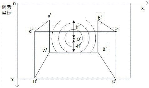
[0025] (2) Nine feature points (3.2) are laid out on the site, and the feature points are arranged around the axis of the depth camera, and are symmetrical in the horizontal direction;

[0026] (3) Collect and record feature point image coordinates and depth data (3.3); through repeated sampling and digital filtering to obtain more accurate values, it is necessary to ensure that the position of the depth camera is fixed while collecting;

[0027] (4) Construct the image space projection (3.4) according to the collected feature point values;

[0...


PUM


Abstract

The invention discloses a 3D machine vision space detection calibration method based on depth vision. Since 9 characteristic points of an on-site standardized physical space are adopted for calibration, and depth information is acquired by using a depth camera, space conversion, coordinate conversion and virtual space generation can be directly completed, the calibration process of 3D machine vision in space detection can be rapidly completed, the calibration complexity can be degraded, and meanwhile the influence of environment variation factors can be effectively avoided on the basis of the actual on-site calibration process.

Description

technical field [0001] The invention relates to a 3D machine vision space detection and calibration method, which belongs to the field of industrial machine vision detection, especially the field of vision detection based on a depth camera. Background technique [0002] With the development of 3D imaging technology, the depth camera based on TOF technology has gradually matured and has begun to be applied in industrial machine vision inspection. At present, in terms of application technologies involving space detection, there are mainly laser radar, laser raster scanning, two-dimensional multi-eye stereo vision synthesis, etc. These technologies have the characteristics of high detection accuracy, complex system, expensive price, low spatial resolution, and complex calculation, while the depth camera based on TOF technology can have a large effective range and fast synchronous measurement at high pixel resolution. Advantages, it has huge advantages in space detection and wo...

Claims


Application Information

Patent Timeline
Patent Type & Authority Applications(China)
IPC IPC(8): G01C11/00G01C25/00
CPCG01C11/00G01C25/00
Inventor 王海宽戚谢鑫张金标
Owner SHANGHAI JIQING HUISHI TECH CO LTD
Learn More