A backlight adjusting method and a backlight drive circuit
A backlight driving circuit and backlight adjustment technology, which is applied to instruments, static indicators, etc., can solve problems such as increasing the complexity of the backlight circuit, and achieve the effect of solving the flickering problem
- Summary
- Abstract
- Description
- Claims
- Application Information
AI Technical Summary
Problems solved by technology
Method used
Image
Examples
Embodiment 1
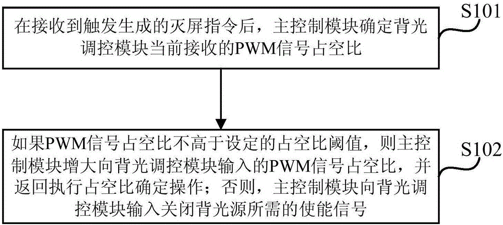
[0021] image 3 The flow diagram of a backlight adjustment method provided in Embodiment 1 of the present invention is applicable to the situation where the screen of the display device changes from bright screen to off screen, and the method can be executed by a backlight driving circuit, wherein the backlight driving circuit can be controlled by software and / or implemented by hardware, and generally integrated in a display device.
[0022] Such as figure 1 As shown, a backlight adjustment method provided by Embodiment 1 of the present invention includes the following operations:
[0023] S101. After receiving the trigger-generated off-screen instruction, the main control module determines the duty cycle of the PWM signal currently received by the backlight control module.
[0024] Generally, the display device can be an electronic device with a backlight, and the backlight can be an LED light, and the state transition of the display device from on-screen to off-screen can...
Embodiment 2
[0033] Figure 4 It is a schematic flowchart of a backlight adjustment method provided by Embodiment 2 of the present invention. This embodiment is optimized on the basis of the above-mentioned embodiments. In this embodiment, the main control module determines that the PWM signal currently received by the backlight adjustment module takes up The specific optimization of the duty ratio is as follows: the determination unit of the main control module determines the duty ratio of the PWM signal currently received by the backlight control module according to the PWM signal currently generated by the main control module.
[0034] On the basis of the above embodiments, the method for adjusting the backlight further includes: the determination unit of the main control module determines whether the duty cycle of the PWM signal is higher than the set duty cycle threshold.
[0035]Further, the main control module increases the duty cycle of the PWM signal input to the backlight control...
Embodiment 3
[0055] Figure 5a It is a structural block diagram of a backlight driving circuit provided by Embodiment 3 of the present invention. Applicable to the situation where the screen of the display device changes from bright screen to off screen, the backlight driving circuit can be realized by software and / or hardware, and is generally integrated in the display device. Such as Figure 5a As shown, the backlight driving circuit includes: an input filter 51 , an energy storage inductor 52 , an output filter 53 and a backlight 54 , and also includes a main control module 55 and a backlight regulation module 56 .
[0056] Wherein, the main control module 55 is connected with the backlight control module 56, and is used for determining and judging the duty cycle of the PWM signal currently received by the backlight control module 56 after receiving the off-screen command generated by the trigger, and generating a PWM signal or enabling Signal.
[0057] The backlight control module 5...
PUM
 Abstract
Description
Claims
Application Information
 - R&D
- Intellectual Property
- Life Sciences
- Materials
- Tech Scout
- Unparalleled Data Quality
- Higher Quality Content
- 60% Fewer Hallucinations
Browse by: Latest US Patents, China's latest patents, Technical Efficacy Thesaurus, Application Domain, Technology Topic, Popular Technical Reports.
© 2025 PatSnap. All rights reserved.Legal|Privacy policy|Modern Slavery Act Transparency Statement|Sitemap|About US| Contact US: help@patsnap.com


