Combination structure of encoder and switch device
A switch device and combined structure technology, applied in the direction of electrical switches, electrical components, circuits, etc., can solve the problems of lack of automatic reset, inconvenient assembly, complex internal structure, etc., and achieve the effect of flexible and simple operation, easy use and simple structure
- Summary
- Abstract
- Description
- Claims
- Application Information
AI Technical Summary
Problems solved by technology
Method used
Image
Examples
Embodiment 1
[0046] Embodiment 1: The encoder and the switch device are detachably snapped together and used together.
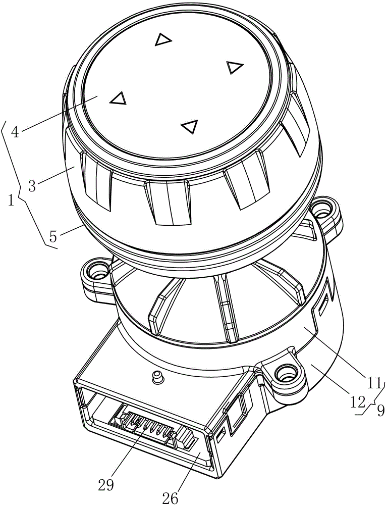
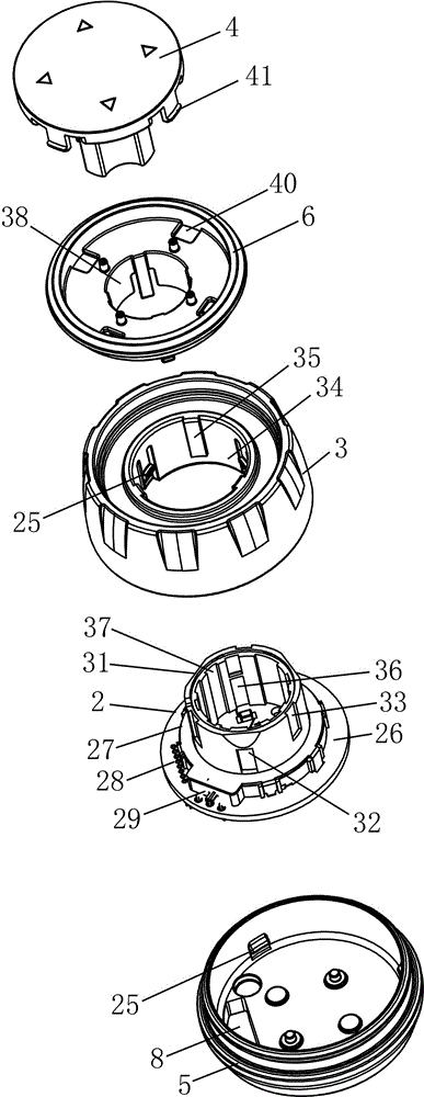
[0047] Such as Figure 1-16 As shown, a combined structure of an encoder and a switch device, including an encoder and a multi-directional switch device;
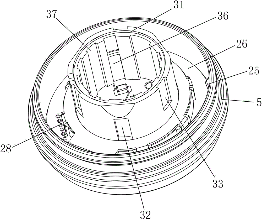
[0048] The encoder includes a knob 1 and an electrical component 2 disposed inside the knob 1, the knob 1 includes a knob body 3, an LED indicator cover 4 and a knob base 5 respectively installed on both sides of the knob body 3, A decorative cover 6 is also provided between the LED indicator cover 4 and the knob body 3, the LED indicator cover 4 is installed on the decorative cover 6, and the decorative cover 6 and the knob body 3 are engaged with each other , the electrical component 2 is fixedly installed in the knob base 5, and the knob base 5 is provided with a connecting portion 7 and an output port 8;
[0049] The multi-directional switch device includes a casing 9 and a four-way swing mechanism 10 arranged i...
Embodiment 2
[0058] Embodiment 2: The encoder and the switch device cannot be used separately;
[0059] Such as Figure 12-24 As shown, a combined structure of an encoder and a switch device, including an encoder and a multi-directional switch device;
[0060] The encoder includes a knob 1 and an electrical component 2 disposed inside the knob 1, the knob 1 includes a knob body 3, an LED indicator cover 4 and a knob base 5 respectively installed on both sides of the knob body 3, A decorative cover 6 is also provided between the LED indicator cover 4 and the knob body 3, the LED indicator cover 4 is installed on the decorative cover 6, and the decorative cover 6 and the knob body 3 are engaged with each other , the electrical component 2 is fixedly installed in the knob base 5, and the knob base 5 is provided with a connecting portion 7 and an output port 8;
[0061] The multi-directional switch device includes a casing 9 and a four-way swing mechanism 10 arranged in the casing 9, the cas...
PUM
 Abstract
Description
Claims
Application Information
 - R&D
- Intellectual Property
- Life Sciences
- Materials
- Tech Scout
- Unparalleled Data Quality
- Higher Quality Content
- 60% Fewer Hallucinations
Browse by: Latest US Patents, China's latest patents, Technical Efficacy Thesaurus, Application Domain, Technology Topic, Popular Technical Reports.
© 2025 PatSnap. All rights reserved.Legal|Privacy policy|Modern Slavery Act Transparency Statement|Sitemap|About US| Contact US: help@patsnap.com


