
LTE antenna with metal frame and mobile terminal

A metal frame and antenna technology, applied in the field of radio frequency, can solve the problems of increasing the antenna space and occupying the battery space in the mobile terminal, etc.

Pending Publication Date: 2017-02-22
GUANGDONG UNIV OF TECH
View PDF8 Cites 7 Cited by
  • Summary
  • Abstract
  • Description
  • Claims
  • Application Information

AI Technical Summary

Problems solved by technology

In order to realize the increase of the above-mentioned operating frequency band, in the prior art, it is usually necessary to increase the headroom height of the antenna, for example, the headroom height is required to be not less than 8mm, but because the headroom height is relatively high, the space where the antenna is located is correspondingly increased. Occupies battery space in mobile terminals

Method used


Image

  • LTE antenna with metal frame and mobile terminal
  • LTE antenna with metal frame and mobile terminal
  • LTE antenna with metal frame and mobile terminal

Examples


Embodiment 1

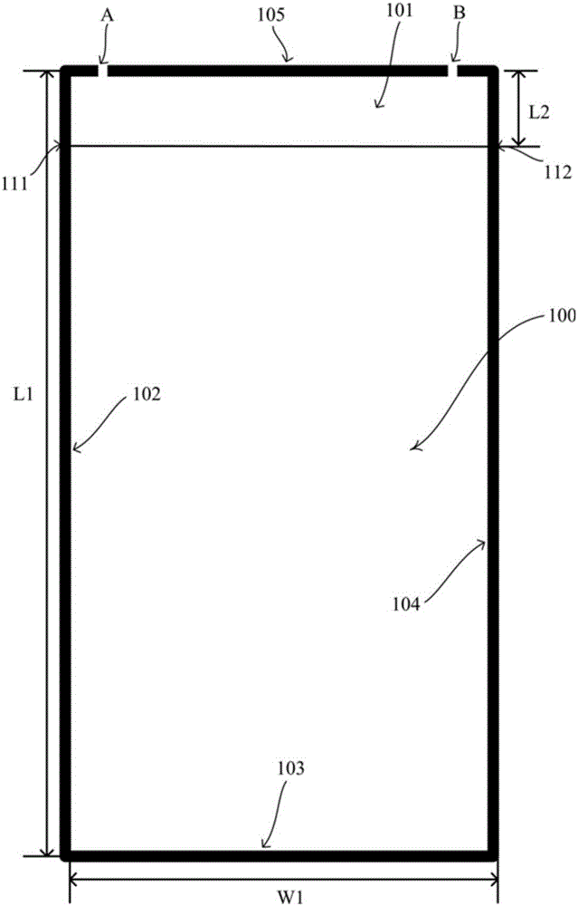
[0034] figure 1 A front view of an LTE antenna with a metal frame provided by an embodiment of the present invention. Such as figure 1 As shown, the LTE antenna with a metal frame includes a metal frame, a PCB board and an antenna part.

[0035] The metal frame includes a first frame 102 , a second frame 103 , a third frame 104 and a fourth frame 105 , which are connected end to end in order to form a frame.

[0036] The PCB board is arranged in the metal frame, and the PCB board includes a metal frame area 100 and a clearance area 101;

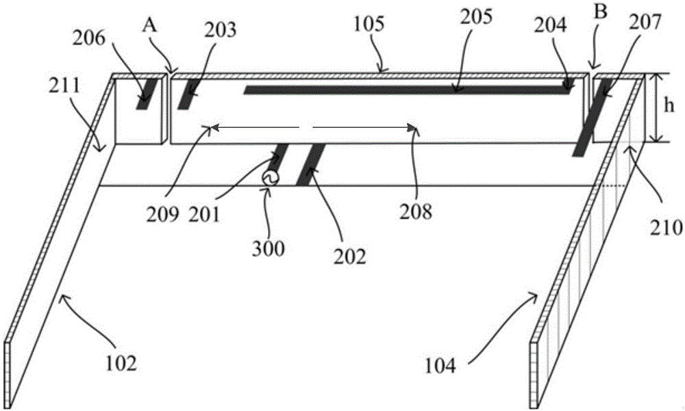
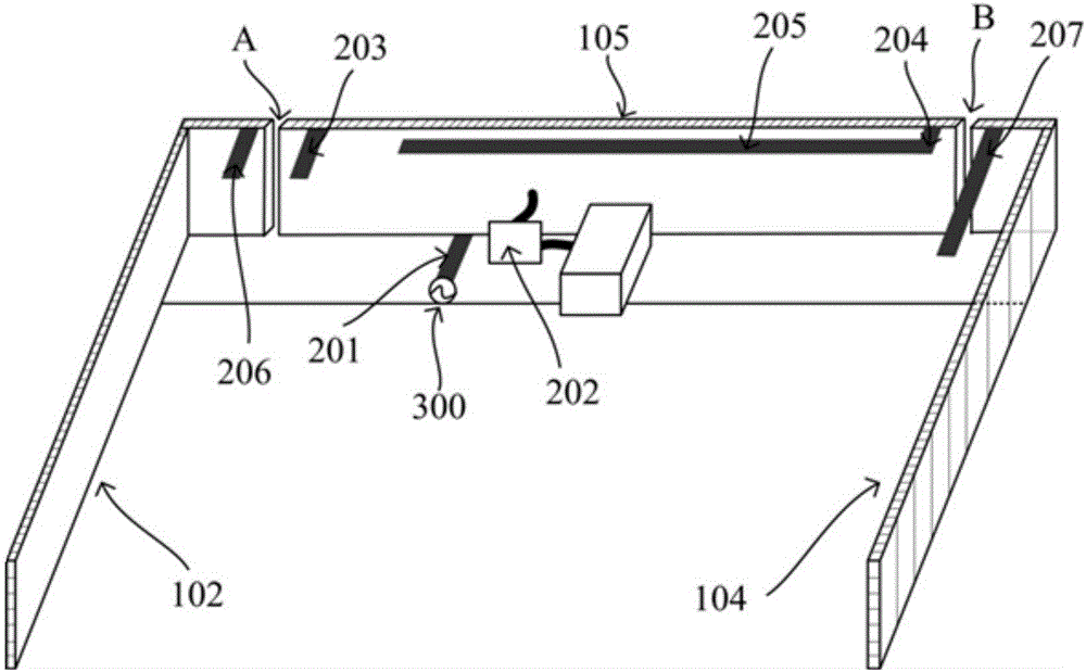
[0037] The antenna part is set in the clearance area 101, including the feed source 300, the feed wire 201 and the antenna.

[0038] The fourth frame 105 has two symmetrical slits, namely a first slit A and a second slit B, and the slits communicate with the clearance area 101 .

[0039] Wherein, the length direction of the fourth frame 105 is perpendicular to the height direction of the clearance area.

[0040] It can be understood that...

Embodiment 2

[0072] A mobile terminal includes a mobile terminal body and the LTE antenna with a metal frame according to Embodiment 1, where the metal frame is the outer frame of the mobile terminal.

[0073] Since the implementation manner of the LTE antenna with a metal frame has been described in detail in Embodiment 1, details are not repeated in this embodiment. Taking a general mobile phone as an example, the size of the mobile phone can be 140mm×70mm, so the metal frame is set as length L1×width W1=140mm×70mm, and the height of the metal frame is h=5mm, such as figure 1 with figure 2 shown.

[0074] Such as figure 1 As shown, the LTE antenna with a metal frame includes a metal frame, a PCB board and an antenna part.

[0075] The mobile terminal provided in this embodiment includes an LTE antenna with a metal frame, the LTE antenna includes a metal frame, a PCB board, and an antenna part; the metal frame includes a first frame, a second frame, a third frame, and a fourth frame, ...


PUM


Abstract

The invention discloses a LTE antenna with a metal frame, and a mobile terminal. The LTE antenna comprises the metal frame, a PCB and an antenna body. The metal frame comprises a first frame body, a second frame body, a third frame body and a fourth frame body which are connected sequentially to form the frame. The PCB is arranged in the metal frame, and the antenna body is arranged in a clearance area and comprises a feed source, a feeder line and an antenna member. The fourth frame body is provided with two symmetrical gaps communicated with the clearance area. Accordingly, the two symmetrical gaps are arranged on the fourth frame body, the resonant path, namely bandwidth and frequency band, of the antenna is expanded. In addition, since the metal frame has the function of radiation, the resonant path of the antenna is further expanded, and the requirement of wide frequency band range of narrow space is met. Accordingly, the LTE antenna with the metal frame has the advantages that the frequency band range of the antenna can be expanded while the height increase of the clearance area is omitted.

Description

technical field [0001] The invention relates to the field of radio frequency technology, in particular to an LTE antenna with a metal frame and a mobile terminal. Background technique [0002] The current mobile terminal usually includes an antenna, and with the diversification and development of mobile terminals, the requirements for the antenna are getting higher and higher. For example, the working frequency bands of the antennas are required to be 824-960MHz and 1710-2700MHz respectively. In order to realize the increase of the above-mentioned working frequency band, in the prior art, it is usually necessary to increase the headroom height of the antenna, for example, the headroom height is required to be not less than 8mm, but because the headroom height is relatively high, the space where the antenna is located is correspondingly increased. It will occupy the space of the battery in the mobile terminal. [0003] It can be seen that how to expand the coverage of the f...

Claims


Application Information

Patent Timeline
IPC IPC(8): H01Q1/44H01Q1/36H01Q5/10H01Q1/22
CPCH01Q1/22H01Q1/36H01Q1/44H01Q5/10
Inventor 吴艳杰黄贝吴多龙温坤华罗文波李健凤田欣欣张勇谭富文
Owner GUANGDONG UNIV OF TECH
Learn More