
Large-sized foldable parabolic antenna

A parabolic antenna and parabolic technology, applied in the direction of folding antennas, antennas, electrical components, etc., can solve the problems of large parabolic antennas occupying a large space, cumbersome disassembly and assembly processes, and poor precision adjustment, so as to improve work efficiency and space utilization High efficiency, low cost, and the effect of ensuring surface accuracy

Inactive Publication Date: 2017-02-22
BEIHANG UNIV
View PDF3 Cites 9 Cited by
  • Summary
  • Abstract
  • Description
  • Claims
  • Application Information

AI Technical Summary

Problems solved by technology

[0003] The purpose of the present invention is to solve the problems that the existing large-scale parabolic antenna occupies a large space in the process of transportation and storage, and the disassembly and assembly process is cumbersome. A large foldable parabolic antenna with a large shrinkage ratio and a modular design

Method used


Image

  • Large-sized foldable parabolic antenna
  • Large-sized foldable parabolic antenna
  • Large-sized foldable parabolic antenna

Examples


Embodiment Construction

[0027] The present invention can be described in further detail below in conjunction with accompanying drawing.

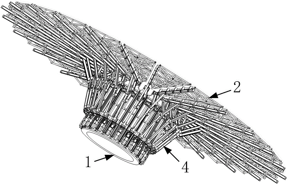
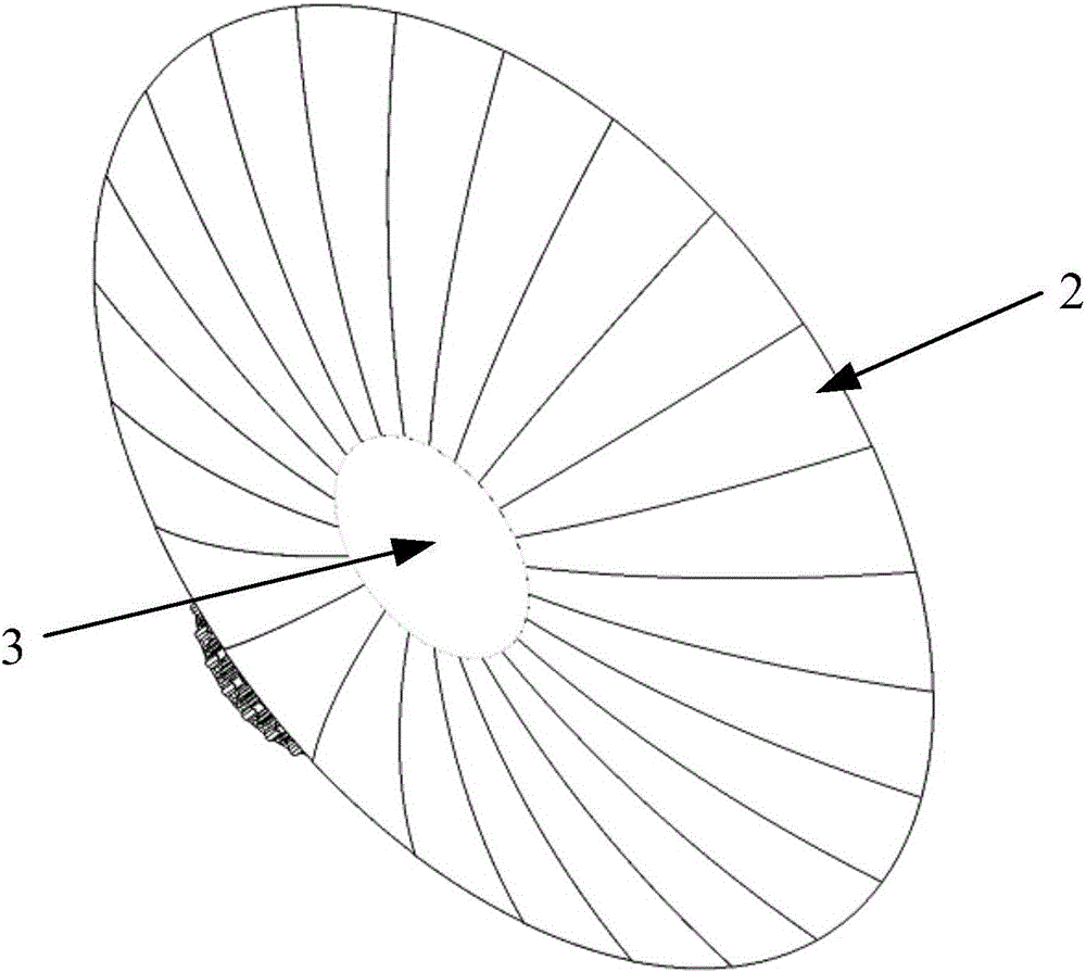
[0028] The large foldable parabolic antenna of the present invention includes a base body 1, a fan-shaped parabolic module 2, a parabolic core 3 and a mechanical linkage mechanism 4, such as figure 1 , figure 2 shown.

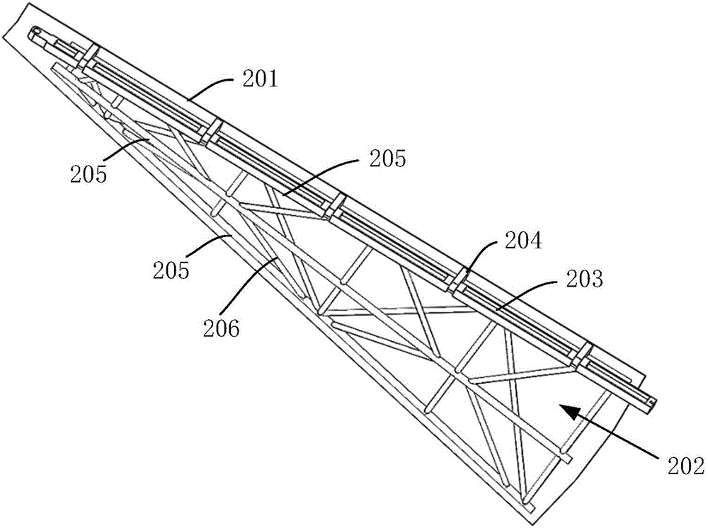
[0029] The base body 1 has a cylindrical structure, and n continuous installation planes are evenly designed on the outer wall in the peripheral direction, which are respectively used for installing n sets of mechanical linkage mechanisms 5 . There are n fan-shaped parabolic surface modules 2, which are evenly arranged in the circumferential direction; one fan-shaped parabolic surface module 2 is installed on each set of mechanical linkage mechanisms 5, and the opening and closing of n fan-shaped parabolic surface modules 2 can be controlled by n sets of mechanical linkage mechanisms 5, such as image 3 shown. The above-mentioned n is a natural ...


PUM


Abstract

The invention discloses a large-sized foldable parabolic antenna, and solves the problem that high-contraction-ratio unfolding and folding of the existing large-sized parabolic antenna cannot be realized due to large occupied space. The large-sized foldable parabolic antenna comprises a base body, fan-shaped parabolic modules, a parabolic center and mechanical connecting rod mechanisms, wherein the multiple mechanical connecting rod mechanisms are uniformly mounted on the outer wall of the base body circumferentially; each mechanical connecting rod mechanism is used for driving one corresponding fan-shaped parabolic module to be opened and folded; meanwhile, the parabolic center is mounted on the top of the base; when n fan-shaped parabolic modules are opened, the n fan-shaped parabolic modules and the parabolic center jointly form the overall parabolic structure; and when the n fan-shaped parabolic modules are folded, the mechanical connecting rod mechanisms also control the corresponding fan-shaped parabolic modules to turn circumferentially so as to enable the adjacent fan-shaped parabolic planes to be mutually overlaid and vertically arranged on the circumferential direction of the base body. The large-sized foldable parabolic antenna has the advantages of capability of realizing quick and automatic folding and extension, high contraction ratio, and capability of ensuring the parabolic plane precision.

Description

technical field [0001] The invention belongs to the field of wireless communication and designs a communication antenna, specifically a large foldable parabolic antenna. Background technique [0002] With the development of social electronic technology and space communication, smaller-diameter parabolic antennas can no longer meet the needs of wireless detection, electronic interference, and electronic attack radar antennas. Large-diameter parabolic antennas have been widely used in ground medium and long-range wireless detection, electronic jamming, and electronic attack military radars, and are developing in the direction of high mobility and rapid response. The diameter of the parabolic surface of the ground medium and long-range wireless detection, electronic interference, and electronic attack military radar is too large, and the antenna must be modularized to meet the requirements of transportation and debugging. If the large parabolic antenna cannot automatically exp...

Claims


Application Information

Patent Timeline
IPC IPC(8): H01Q15/16H01Q1/08
CPCH01Q15/161
Inventor 王巍李雪鹏曹志宏朱佩华王林青孟凡光
Owner BEIHANG UNIV
Learn More