Method, device and system for increasing uplink rate
A rate and user terminal technology, applied in the communication field, can solve the problems of inability to measure a single uplink carrier, inability to perform downlink measurement, and lack of reference path loss for uplink power control.
- Summary
- Abstract
- Description
- Claims
- Application Information
AI Technical Summary
Problems solved by technology
Method used
Image
Examples
Embodiment 1
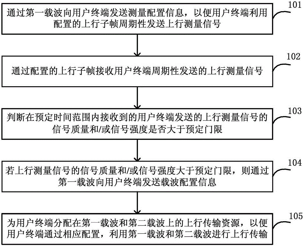
[0219] This embodiment mainly describes the process of adding uplink CA (Carrier Aggregation, Carrier Aggregation) for the terminal on the base station side according to the measurement result of the terminal. The network architecture is as follows: Figure 8 As shown, including the terminal UE1 and the base station eNB1, the base station is configured with two carriers, which are a paired spectrum carrier F1, and the operator configures it to be used in LTE FDD mode, and the other carrier is an asymmetrical carrier F2. Located between TD-LTE and LTE FDD uplink spectrum, the operator configures it to be used in TD-LTE mode, in which the coverage of F2 carrier is smaller than that of F1.
[0220] 1) The eNB1 determines that the UE1 supports a single uplink transmission function on the F2 according to the capability reported by the UE1.
[0221] 2) UE1 is currently working on the carrier F1 of eNB1. According to the downlink RSRP (Reference Signal Receiving Power, reference sign...
Embodiment 2
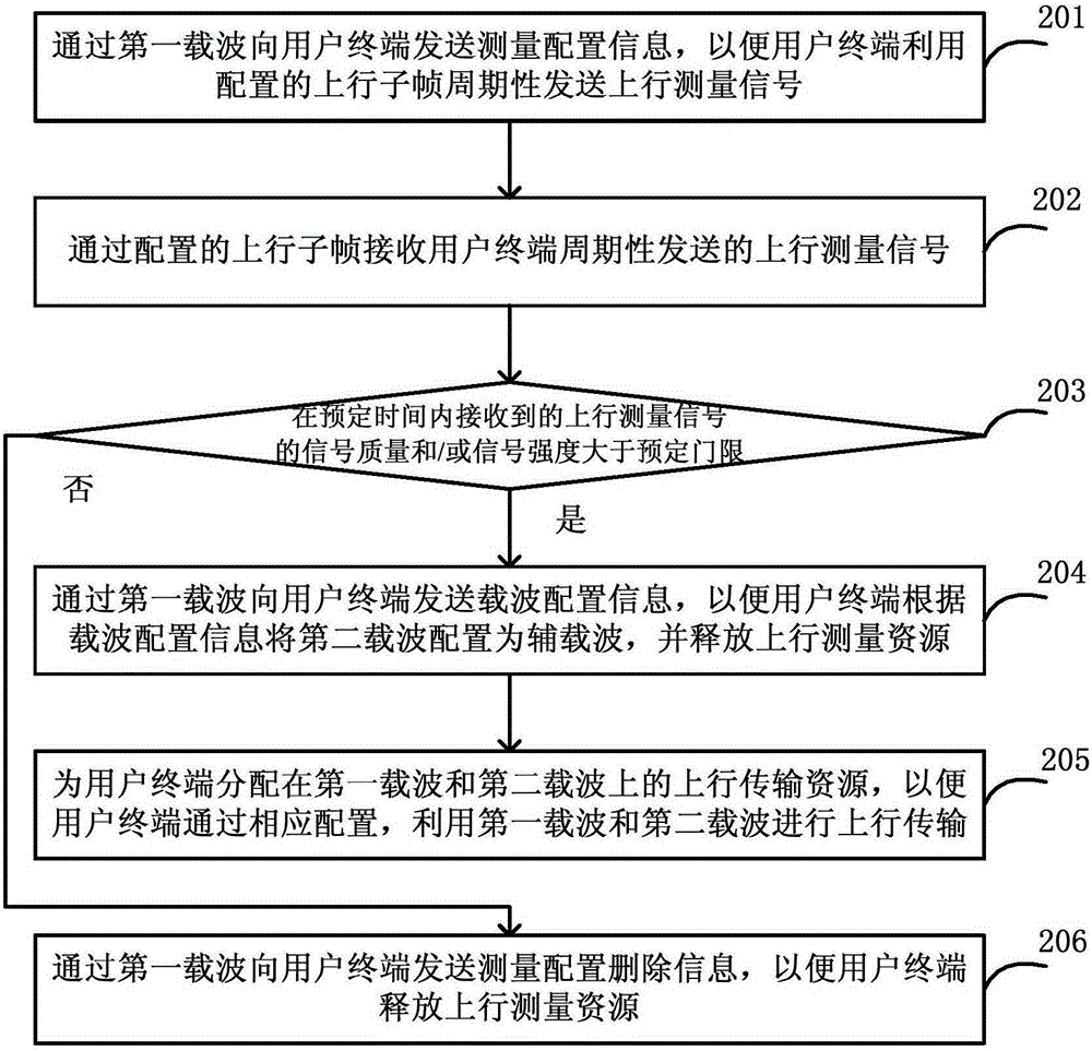
[0244] This embodiment mainly describes the process of deleting the measurement configuration because the uplink performance of the terminal cannot meet the measurement requirements during the process of adding uplink CA for the terminal on the base station side according to the measurement results of the terminal. The network architecture is as follows: Figure 8 As shown, including the terminal UE1 and the base station eNB1, the base station is configured with two carriers, which are a paired spectrum carrier F1, and the operator configures it to be used in LTE FDD mode, and the other carrier is an asymmetrical carrier F2. Located between TD-LTE and LTE FDD uplink spectrum, the operator configures it to be used in TD-LTE mode, in which the coverage of F2 carrier is smaller than that of F1.
[0245] 1) The eNB1 determines that the UE1 supports a single uplink transmission function on the F2 according to the capability reported by the UE1.
[0246] 2) UE1 is currently working ...
Embodiment 3
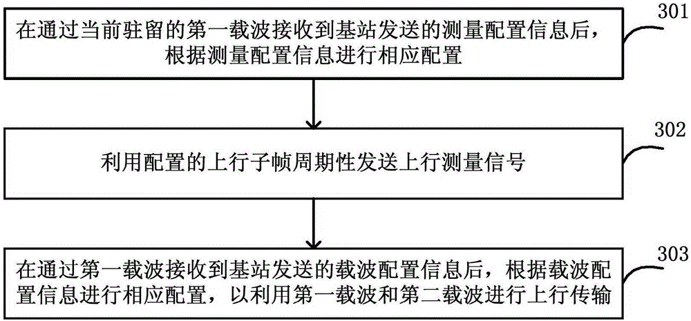
[0261] This embodiment mainly describes the process of adding uplink CA on the terminal side. The network architecture is as follows: Figure 8 As shown, including the terminal UE1 and the base station eNB1, the base station is configured with two carriers, which are a paired spectrum carrier F1, and the operator configures it to be used in LTE FDD mode, and the other carrier is an asymmetrical carrier F2. Located between TD-LTE and LTE FDD uplink spectrum, the operator configures it to be used in TD-LTE mode, in which the coverage of F2 carrier is smaller than that of F1.
[0262] 1) When UE1 initially connects to the network, it indicates to the network information about its terminal capabilities through a NAS message, where the terminal capability information includes the following content:
[0263] Frequency number that supports this capability: the BAND to which F2 belongs
[0264] Whether to support only sending uplink information: 1
[0265] 2) UE1 receives the RR...
PUM
 Abstract
Description
Claims
Application Information
 - R&D
- Intellectual Property
- Life Sciences
- Materials
- Tech Scout
- Unparalleled Data Quality
- Higher Quality Content
- 60% Fewer Hallucinations
Browse by: Latest US Patents, China's latest patents, Technical Efficacy Thesaurus, Application Domain, Technology Topic, Popular Technical Reports.
© 2025 PatSnap. All rights reserved.Legal|Privacy policy|Modern Slavery Act Transparency Statement|Sitemap|About US| Contact US: help@patsnap.com


