
Method, device and system for increasing uplink rate

A rate and user terminal technology, applied in the field of communication, can solve problems such as the lack of reference path loss for uplink power control, carrier incompatibility with traditional terminals, and increased power consumption of terminals.

Active Publication Date: 2019-04-12
CHINA TELECOM CORP LTD
View PDF6 Cites 0 Cited by
  • Summary
  • Abstract
  • Description
  • Claims
  • Application Information

AI Technical Summary

Problems solved by technology

[0003] Whether a carrier that can work independently is configured as TDD (Time Division Duplexing, Time Division Duplex) or FDD, the carrier must contain uplink and downlink transmission resources. If it is only configured for one-way transmission, especially for one uplink direction, then It will cause the carrier to be incompatible with traditional terminals. In theory, it must be applied with other traditional carriers such as carrier aggregation.
But even so, the use of a single uplink carrier and other compatible carrier aggregation still poses a big challenge to the current 3GPP (The 3rd Generation Partnership Project, 3rd Generation Partnership Project) specification:
[0004] [1] It is impossible to measure a single uplink carrier: the measurement configuration issued by the network side in the current specification is based on the downlink. The main reason is that whether the terminal can access mainly refers to the downlink signal. Only after the carrier is synchronized can the timing of uplink transmission be determined in advance. For a single uplink carrier, due to the lack of downlink subframes, downlink measurement cannot be performed, and continuous transmission of uplink signals will greatly increase the power consumption of the terminal
[0005] [2], There is no reference basis for the activation and deactivation of carriers: the activation and deactivation of uplink and downlink carriers in carrier aggregation are triggered based on the activation of downlink carriers, so a single uplink carrier cannot reuse the current 3GPP specification to determine Whether the uplink carrier meets the conditions for activation or deactivation
[0006] [3] Lack of reference path loss for uplink power control: When the UE (User Equipment, user terminal) supports uplink carrier aggregation, regardless of whether the UE supports cross-carrier scheduling, the UE must support configuring the secondary carrier to use the downlink of the cell As a reference for downlink path loss, there is no downlink carrier as a reference for a single uplink carrier, so the current specification cannot be reused

Method used


Image

  • Method, device and system for increasing uplink rate
  • Method, device and system for increasing uplink rate
  • Method, device and system for increasing uplink rate

Examples


Embodiment 1

[0219] This embodiment mainly describes the process of adding uplink CA (CarrierAggregation, carrier aggregation) for the terminal on the base station side according to the measurement result of the terminal. The network architecture is as follows: Figure 8 As shown, including the terminal UE1 and the base station eNB1, the base station is configured with two carriers, which are a paired spectrum carrier F1, and the operator configures it to be used in LTE FDD mode, and the other carrier is an asymmetrical carrier F2. Located between TD-LTE and LTE FDD uplink spectrum, the operator configures it to be used in TD-LTE mode, in which the coverage of F2 carrier is smaller than that of F1.

[0220] 1) The eNB1 determines that the UE1 supports a single uplink transmission function on the F2 according to the capability reported by the UE1.

[0221] 2) UE1 is currently working on the carrier F1 of eNB1. According to the downlink RSRP (Reference Signal Receiving Power, reference signa...

Embodiment 2

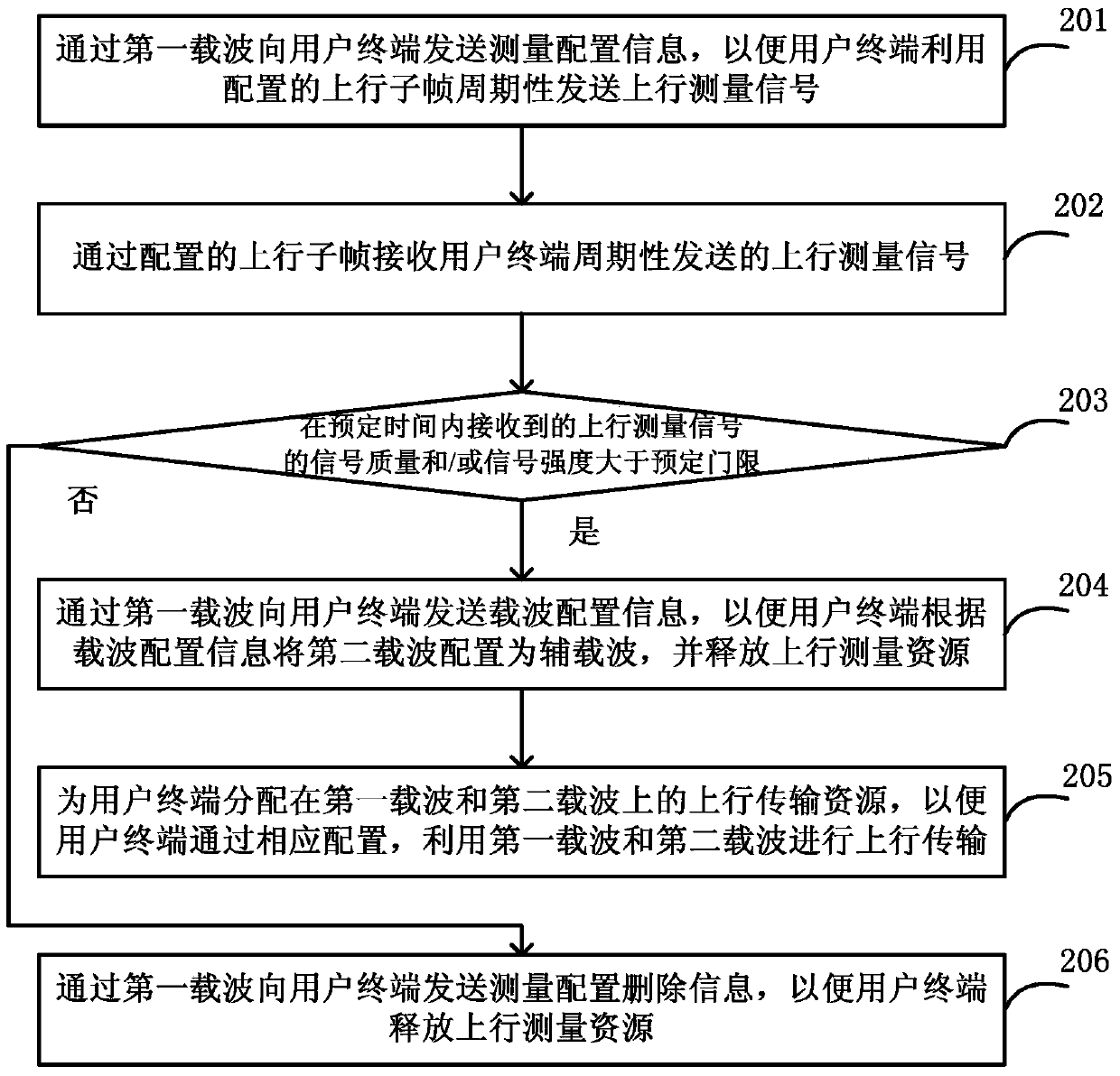
[0244] This embodiment mainly describes the process of deleting the measurement configuration because the uplink performance of the terminal cannot meet the measurement requirements during the process of adding uplink CA for the terminal on the base station side according to the measurement results of the terminal. The network architecture is as follows: Figure 8 As shown, including the terminal UE1 and the base station eNB1, the base station is configured with two carriers, respectively a paired spectrum carrier F1, which is configured by the operator to use LTE FDD, and the other carrier is an asymmetrical carrier F2, which is located at Between TD-LTE and LTE FDD uplink spectrum, the operator configures it to be used as TD-LTE, and the coverage of F2 carrier is smaller than that of F1.

[0245] 1) The eNB1 determines that the UE1 supports a single uplink transmission function on the F2 according to the capability reported by the UE1.

[0246] 2) UE1 is currently working on...

Embodiment 3

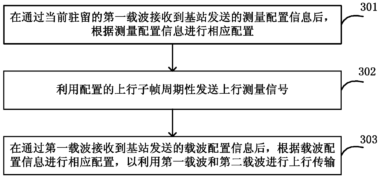
[0261] This embodiment mainly describes the process of adding uplink CA on the terminal side. The network architecture is as follows: Figure 8 As shown, including the terminal UE1 and the base station eNB1, the base station is configured with two carriers, respectively a paired spectrum carrier F1, which is configured by the operator to use LTE FDD, and the other carrier is an asymmetrical carrier F2, which is located at Between TD-LTE and LTE FDD uplink spectrum, the operator configures it to be used as TD-LTE, and the coverage of F2 carrier is smaller than that of F1.

[0262] 1) When UE1 initially connects to the network, it indicates to the network information about its terminal capabilities through a NAS message, where the terminal capability information includes the following content:

[0263] Frequency number that supports this capability: the BAND to which F2 belongs

[0264] Whether to support only sending uplink information: 1

[0265] 2) UE1 receives the RRC ...


PUM


Abstract

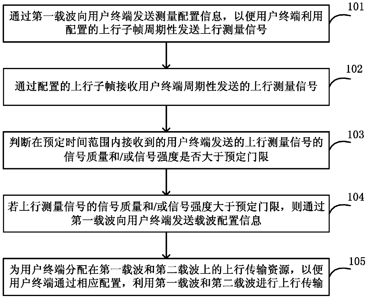
The invention discloses a method, a device and a system for increasing the uplink rate. A base station sends measurement configuration information to user equipment through a first carrier so that the user equipment can use a configured uplink sub-frame to send an uplink measurement signal periodically, wherein the configured uplink sub-frame is included in an uplink sub-frame set which can be transmitted on a second carrier. When judging that the signal quality and / or signal intensity of the uplink measurement signal received within a predetermined time range are / is higher than a predetermined threshold, the base station sends carrier configuration information to the user equipment through the first carrier so the user equipment can configure the second carrier as an auxiliary carrier according to the carrier configuration information. The base station allocates uplink transmission resources on the first carrier and on the second carrier for the user equipment so the user equipment can use both the first carrier and the second carrier to carry out uplink transmission through corresponding configuration. Thus, the user's uplink rate is increased effectively, and the user's uplink rate experience is enhanced under the condition of low design complexity.

Description

technical field [0001] The present invention relates to the communication field, in particular to a method, device and system for increasing the uplink rate. Background technique [0002] In the current frequency division of LTE (Long Term Evolution, Long Term Evolution), especially between TD-LTE (Time Division-LTE, Time Division Long Term Evolution) and LTE FDD (Frequency Division Duplexing, Frequency Division Duplexing) frequencies usually need to set a protection band, thereby solving the interference coexistence problem between the two systems. According to the common spectrum allocation scheme at home and abroad, the size of the guard band is usually 5MHz, and in some special scenarios, a guard band of 10MHz or larger needs to be reserved. At present, the spectrum resources of low and medium frequencies are already very tight, and the use of guard bands reduces the available spectrum. Therefore, how to effectively use guard band resources and reduce interference to ad...

Claims


Application Information

Patent Timeline
Patent Type & Authority Patents(China)
IPC IPC(8): H04L5/00
CPCH04L5/0008H04L5/0037
Inventor 许森孙震强张光辉
Owner CHINA TELECOM CORP LTD
Learn More