
Visual automatic bending alignment mechanism

A technology of visual alignment and bending mechanism, applied in the direction of electrical components, printed circuit manufacturing, printed circuit, etc., can solve the problems of inaccurate positioning, difficult to control the size of the force, low production efficiency, etc., to achieve high market competitiveness, Ensure the accuracy and ensure the effect of bending quality

Active Publication Date: 2017-02-22
东莞东聚电子电讯制品有限公司
View PDF5 Cites 8 Cited by
  • Summary
  • Abstract
  • Description
  • Claims
  • Application Information

AI Technical Summary

Problems solved by technology

The traditional bending is directly operated by the operator. Due to the particularity of the material of the flexible printed circuit board, it is difficult to control the magnitude of the force when bending directly by hand, and the expected effect cannot be achieved on the bending radius and bending position. Low production efficiency and poor product consistency
[0007] With the development of automated production technology, mechanical mechanisms are currently used to bend flexible printed circuit boards, but the positioning is not accurate, that is, the accuracy of bending alignment cannot be guaranteed, so that the bending quality cannot be guaranteed, so that it cannot It satisfies processing needs very well and is not conducive to improving market competitiveness

Method used

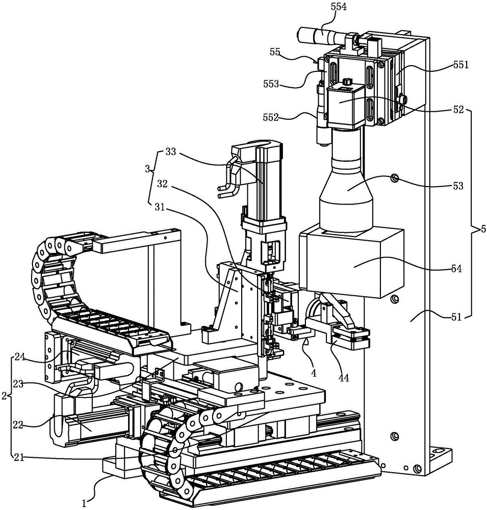

Image

  • Visual automatic bending alignment mechanism
  • Visual automatic bending alignment mechanism
  • Visual automatic bending alignment mechanism

Examples


Embodiment Construction

[0026] The present invention will be further described below in conjunction with specific embodiments and accompanying drawings.

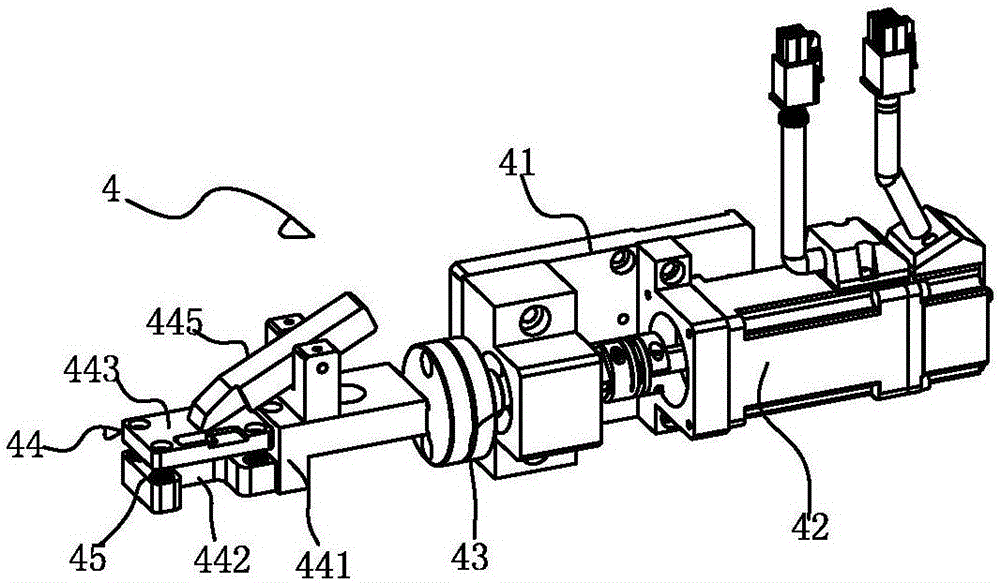
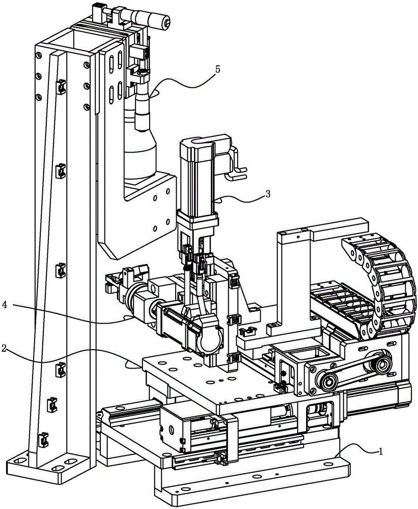
[0027] See Figure 1-3 As shown, it is a visual automatic bending alignment mechanism, which includes: a base 1, an XY moving platform mechanism 2 installed on the upper end of the base 1, and a clamping folding mechanism installed on the XY moving platform mechanism 2 through a Z-axis driving mechanism 3. The bending mechanism 4 and the visual alignment mechanism 5 installed on the side of the base 1, the visual alignment mechanism 5 cooperates with the XY moving platform mechanism 2 to automatically shift and compensate the clamping bending mechanism 4, so that the bending alignment can be ensured High precision and guaranteed bending quality make the invention highly competitive in the market.

[0028] The XY mobile platform mechanism 2 includes an X-axis mobile platform 21 mounted on the base 1 in a movable manner in the X-axis direction, moun...


PUM


Abstract

The invention discloses a visual automatic bending alignment mechanism which comprises a base, an XY mobile platform mechanism mounted at the upper end of the base, a clamping bending mechanism mounted on the XY mobile platform mechanism through a Z-axis drive mechanism and a visual alignment mechanism mounted beside the base, wherein the visual alignment mechanism cooperates with the XY mobile platform mechanism to perform automatic shift compensation for the clamping bending mechanism; and the clamping bending mechanism comprises a mounting seat mounted on the Z-axis drive mechanism, a drive motor mounted on the mounting seat, a speed reducer and a bending chuck detachably assembled with the speed reducer. In the invention, the visual alignment mechanism photographs the state of the bending chuck after selecting a bending flexible printed circuit board to capture the features, and calculates the position; and then, the XY mobile platform mechanism performs automatic shift compensation for the clamping bending mechanism according to the data obtained by the visual alignment mechanism, so that the accuracy of bending alignment can be guaranteed, the bending quality is guaranteed, and the market competitiveness is remarkably high.

Description

[0001] Technical field: [0002] The invention relates to the technical field of automatic production, in particular to a visual automatic bending alignment mechanism. [0003] Background technique: [0004] As we all know, FPC (Flexible Printed Circuit: flexible printed circuit board), also known as flexible circuit board, flexible circuit board, referred to as soft board, has the characteristics of high wiring density, light weight and thin thickness. [0005] At present, the internal space of the structural design of electronic products such as the mobile phone industry is becoming more and more compact. Therefore, it is not only required to control the tolerance between the component bodies of electronic products, but also to require the connecting wires of the components themselves (usually flexible printed circuit boards) to be able to fold It is bent into a perfect fit with the gap, so as to meet the design requirements for smooth assembly. [0006] In the traditional p...

Claims


Application Information

Patent Timeline
Patent Type & Authority Applications(China)
IPC IPC(8): H05K3/00
CPCH05K3/0014
Inventor 傅健鹏张良平夏常胜
Owner 东莞东聚电子电讯制品有限公司
Learn More