Filter structure with enhanced dirt holding capacity
A filter layer, fiber filtration technology, applied in membrane filters, cartridge filters, fixed filter element filters, etc., can solve problems such as increase in filter volume
- Summary
- Abstract
- Description
- Claims
- Application Information
AI Technical Summary
Problems solved by technology
Method used
Image

Examples
Embodiment 1
[0086] Example 1 provides exemplary procedures for preparing nylon solutions for electrospinning according to certain embodiments of the present invention.
[0087] Nylon 6 was supplied by BASF Corp., Florham Park, NJ, USA under the trademark Ultramid B24. Solutions of Nylon 6 were prepared in a mixture of two solvents, acetic acid and formic acid, present in a weight ratio of 2:1. To produce fibers with a diameter of approximately 120 nm, a solution of 11% by weight nylon 6 was prepared, to produce fibers with a diameter of approximately 160 nm, a solution of 12.4% by weight nylon 6 was prepared, and to produce fibers with a diameter of approximately 200 nm, a solution of 13.7% by weight was prepared. Solutions were prepared by vigorously stirring each mixture of solvent and polymer at 80 °C for 5 to 6 hours in a glass reactor. The solution was then cooled to room temperature.
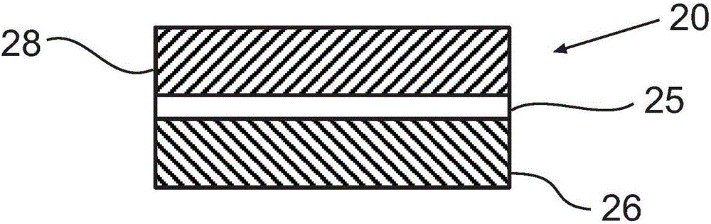
[0088] In Example 1, a nylon nanofiber mat is made of nanofibers having two different fiber diam...
Embodiment 2
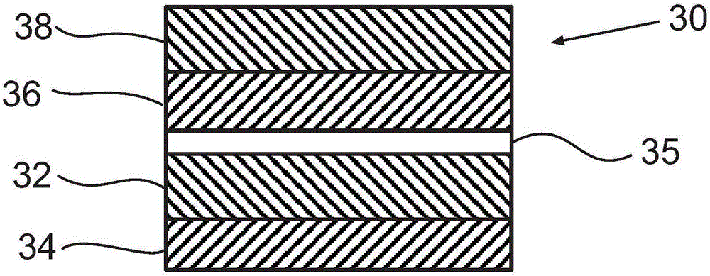
[0094] Example 2 further demonstrates the advantage of including a rough porous interlayer between two filter layers, wherein in addition to the mats containing fibers of approximately 120 nm and 200 nm in diameter of Example 1, an additional mat containing nanofibers, approximately 20 Micron thick, containing fibers approximately 160 nm in diameter. This additional pad containing nanofibers was placed between the pad containing 120 nm fibers and the pad containing 200 nm fibers.
[0095] figure 2 A first set of filtration devices is illustrated in which nanofiber-containing mats are layered directly on top of each other. For the second set of filter devices, a coarse polypropylene nonwoven layer with an approximate fiber diameter of about 5 μm to 10 μm was placed between the mat containing 120 nm fibers and the mat containing 160 nm fibers, and between the mat containing 160 nm fibers and the mat containing 200 nm fibers. between the pads. As in Example 1, all filter stru...
Embodiment 3
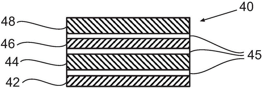
[0098] Example 3 also demonstrates the advantage of including a rough porous interlayer between two filter layers. The three nanofiber layers described in Example 2 were arranged such that an approximately 75 μm thick nylon nonwoven interlayer composed of fibers with a fiber diameter of approximately 15 μm to 20 μm was placed adjacent to the 160 nm nanofiber layer. In another variation, the nylon nonwoven interlayer is disposed only between the 160nm and 120nm nanofiber layers, and the 200nm nanofiber layer is disposed adjacent to the 160nm nanofiber layer.
[0099] The throughput capabilities of these two filtration structures were measured as described in Example 1, and were compared to those in which there was no nonwoven interlayer (i.e., three nanofiber layers adjacent to each other) and those containing nanofiber layers arranged at 160 nm and 120 nm. The filtering structures between are compared.
[0100] Figure 4 The composite media filter structure illustrating the ...
PUM
| Property | Measurement | Unit |
|---|---|---|
| diameter | aaaaa | aaaaa |
| thickness | aaaaa | aaaaa |
| diameter | aaaaa | aaaaa |
Abstract
Description
Claims
Application Information
 - R&D Engineer
- R&D Manager
- IP Professional
- Industry Leading Data Capabilities
- Powerful AI technology
- Patent DNA Extraction
Browse by: Latest US Patents, China's latest patents, Technical Efficacy Thesaurus, Application Domain, Technology Topic.
© 2024 PatSnap. All rights reserved.Legal|Privacy policy|Modern Slavery Act Transparency Statement|Sitemap