Valve arrangement

A valve assembly and discharge valve technology, applied in the directions of safety valve, balance valve, valve device, etc., can solve the problems of valve assembly occupation, huge construction cost, installation cost and maintenance cost, large installation space, etc., to achieve space saving, high Dynamic performance, effect of short installation error chains

Active Publication Date: 2017-02-22
ROBERT BOSCH GMBH
View PDF12 Cites 0 Cited by
  • Summary
  • Abstract
  • Description
  • Claims
  • Application Information

AI Technical Summary

Problems solved by technology

This leads, on the one hand, to the large installation space occupied by the valve assembly and, on the other hand, to an increased possibility of errors,

Method used


Image

  • Valve arrangement
  • Valve arrangement
  • Valve arrangement

Examples


Embodiment Construction

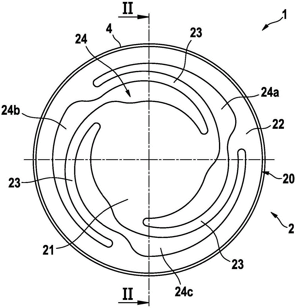
[0031] Next refer to figure 1 and 2 The valve assembly 1 according to the first preferred embodiment of the present invention is explained in detail.

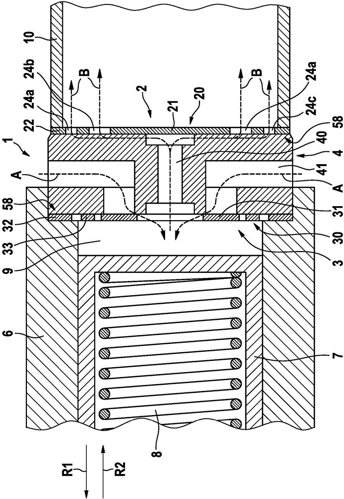
[0032] figure 1 A top view of a valve assembly 1 according to the invention is shown. figure 2 shown from the left figure 1 A cross-sectional view of the valve assembly 1 , wherein the piston 7 with the reset element 8 and the outlet opening 10 arranged in the cylinder 6 are schematically additionally shown in section for explaining the mode of operation of the valve assembly 1 .

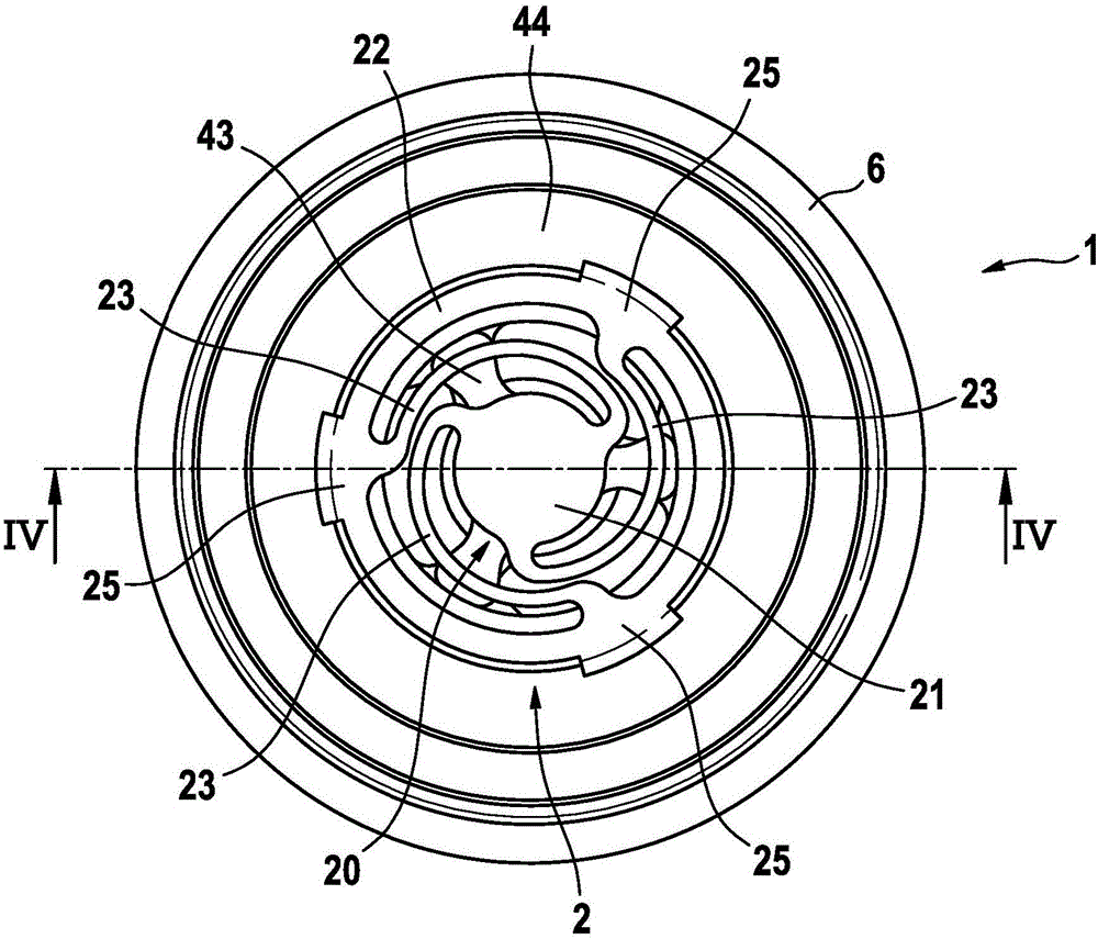
[0033] as from figure 2 and partly from figure 1 As can be clearly seen in FIG. 1 , the valve assembly 1 has an outlet valve 2 , an inlet valve 3 and a valve carrier 4 with a through-opening 40 . According to the invention, outlet valve 2 comprises a first diaphragm spring 20 .

[0034] exist figure 1 The first diaphragm spring 20 , better seen in , has a first inner sealing portion 21 , a first outer support portion 22 and three first spri...


PUM


Abstract

The present invention concerns a valve arrangement comprising an outlet valve (2), an inlet valve (3) and a valve support (4) with a passageway, the outlet valve (2) being arranged on the valve support (4). According to the invention, the outlet valve (2) comprises a first diaphragm spring (20).

Description

technical field [0001] The invention relates to a valve assembly which may be used, for example, in a fuel pump for a vehicle, and to a fuel pump comprising such a valve assembly. Background technique [0002] Such a valve assembly or such a fuel pump is known, for example, from GB 2478876B. Here, the fuel pump in the form of an electromagnetic piston pump comprises a valve assembly with an inlet valve, an outlet valve and a valve carrier with a through-opening, wherein the outlet valve is arranged on the valve carrier. Furthermore, the outlet valve is designed as a ball valve with a reset element and is correspondingly assembled from several components. This leads, on the one hand, to the valve assembly taking up a large installation space and, on the other hand, to an increased possibility of errors, for example during installation of the valve assembly into the fuel pump. This results in enormous construction, installation and maintenance costs. Contents of the invent...

Claims


Application Information

Patent Timeline
IPC IPC(8): F16K17/18
Inventor S·芙洛F·尼切J·阿尔塔莫诺夫S·阿克居尔L·M·贝斯勒T·阿尔盖尔A·普利施F·许默
Owner ROBERT BOSCH GMBH
Why Eureka
Try Eureka