Supercharge Your Innovation With Domain-Expert AI Agents!

Fiber optic cable assembly for terminating fiber optic cable and method of manufacture

A fiber optic cable and cable technology, applied in the coupling of optical components, optical waveguides, optics, etc., can solve the problems of different combinations, difficult to use connectors to terminate cables, not easy, etc.

Active Publication Date: 2018-08-28
CORNING OPTICAL COMM LLC
View PDF5 Cites 0 Cited by
  • Summary
  • Abstract
  • Description
  • Claims
  • Application Information

AI Technical Summary

Problems solved by technology

[0004] Fiber optic connectors may be designed to terminate one particular fiber optic cable design, and therefore may not be easily adapted to terminate other fiber optic cable designs
For example, fiber optic cable designs may have different cross-sectional shapes, cross-sectional dimensions, and / or materials, and fiber optic connectors intended for a particular cable design may not be easily adapted for use in other cable designs
Even different fiber optic cables of the same design can have manufacturing variations that can make it difficult to terminate that cable design with certain connectors
Additionally, customers may want to use a specific fiber optic connector for their network, but incorporate a different cable design than the cable designed to work with their preferred connector

Method used


Image

  • Fiber optic cable assembly for terminating fiber optic cable and method of manufacture
  • Fiber optic cable assembly for terminating fiber optic cable and method of manufacture
  • Fiber optic cable assembly for terminating fiber optic cable and method of manufacture

Examples


Embodiment Construction

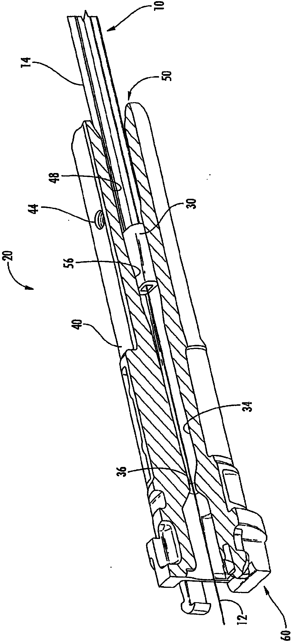
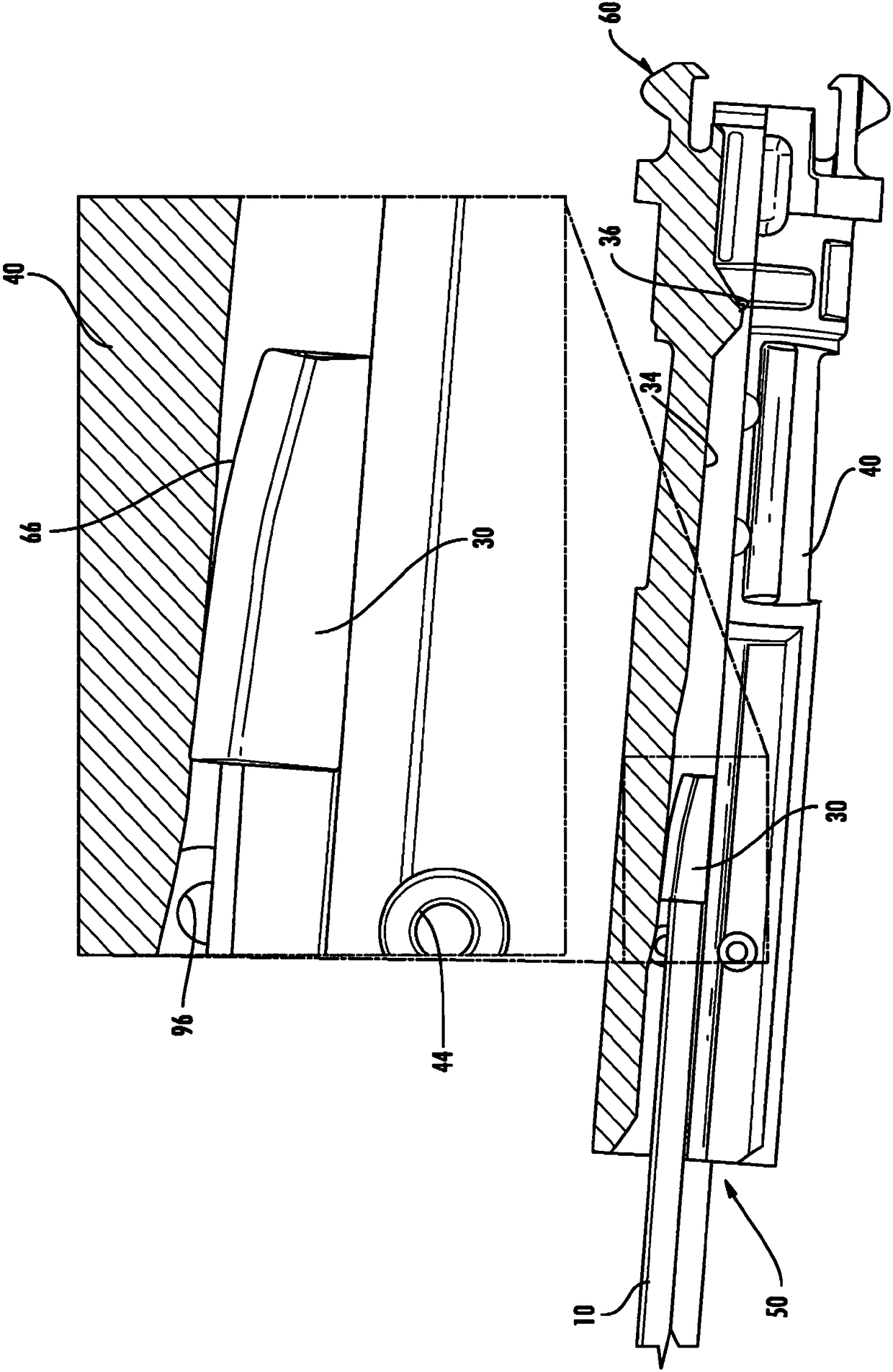
[0026] figure 1 is a cutaway view showing the steps of terminating the cable 10 according to the first embodiment. For example, cable 10 may be a fiber optic cable having, for example, one or more optical transmission components, such as one or more optical fibers 12 . Instead of, or in addition to, optical transmission components, other data, voice, etc., and other information transmission media, like metallic conductors for example, may be included. In the illustrated embodiment, the optical transmission component comprises a plurality of optical fibers 12 . The cable 10 may also have, for example, a polymer jacket 14 and one or more pigtails or strength members 16 ( Figure 8 shown in ).

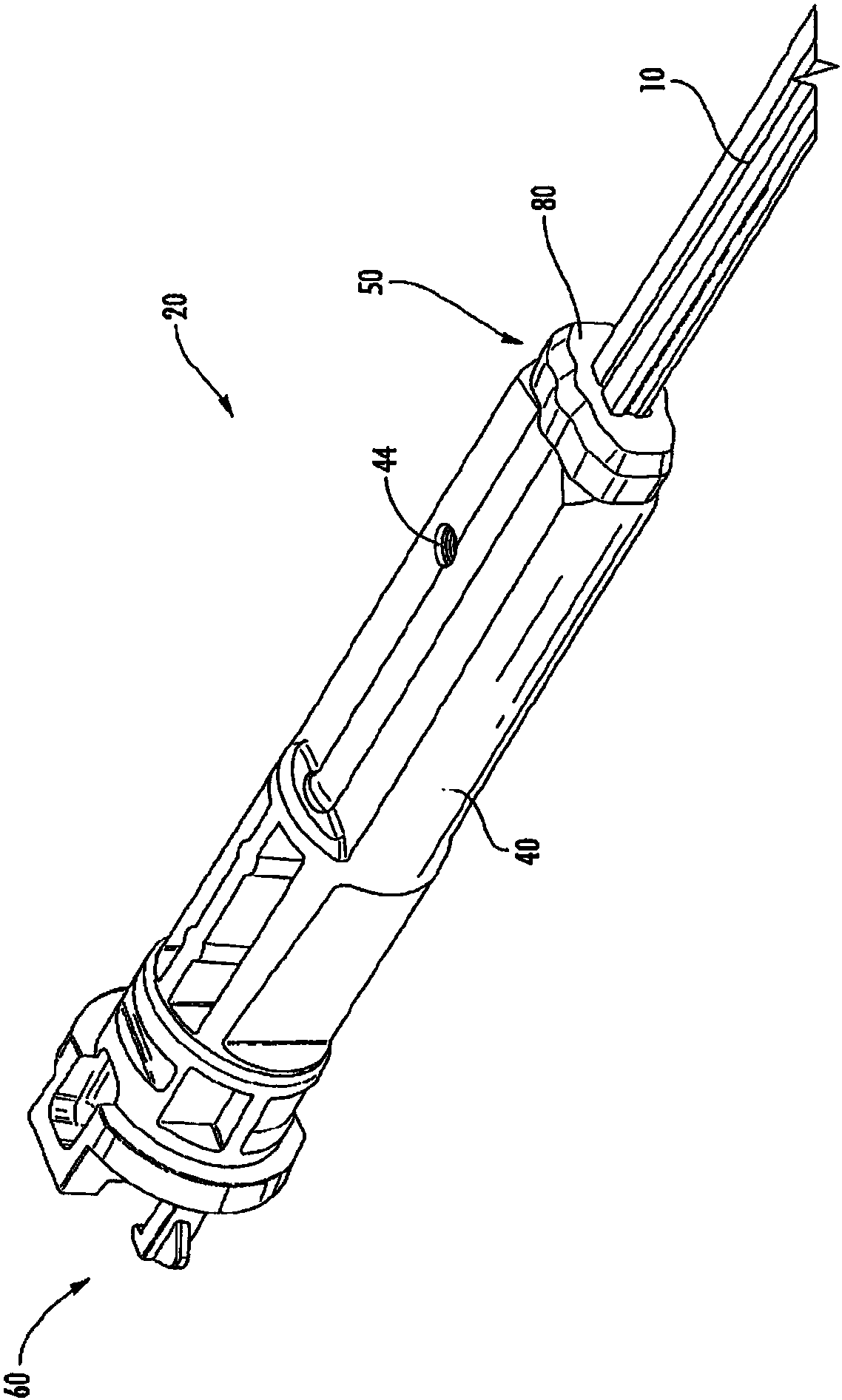
[0027] figure 2 is a perspective view of a subassembly of a terminated cable 20 (also known as a "connectorized" cable). The sub-assemblies may ultimately be formed into fiber optic cable assemblies having hardened fiber optic connectors at their ends ( Figure 12 shown in ). refe...


PUM

PropertyMeasurementUnit
Shore hardnessaaaaaaaaaa

Abstract

A fiber optic cable assembly for terminating a cable using an internal sealing member in a channel of a holding body and method of manufacturing the same. The inner sealing member inhibits penetration of bonding material to unintended portions of the retention body and also serves to position the cable within the retention body during a termination process. Embodiments may include optional end seals for inhibiting adhesive from escaping the retaining body.

Description

[0001] priority application [0002] This application claims the benefit under the Patents Act of US Provisional Application Serial No. 61 / 991,974, filed May 12, 2014, the contents of which are upon which this application is based and incorporated herein by reference in its entirety. Background technique [0003] Fiber optic connectors are an integral part of fiber optic communication systems and are used to terminate optical transmission components, such as optical fibers of fiber optic cables. Fiber optic connectors are widely used to provide paired / unpaired connection points in optical networks, to connect different optical fibers, and to terminate optical fibers for optical connection with other devices, such as closures, multiports, optical transmitters, receivers, isolation amplifiers, attenuators, amplifiers, power meters and detectors. When terminating a fiber optic cable with a fiber optic connector, the fiber optic cable should be secured to the fiber optic connecto...

Claims


Application Information

Patent Timeline
Patent Type & Authority Patents(China)
IPC IPC(8): G02B6/38G02B6/44
CPCG02B6/3887G02B6/3821G02B6/44775G02B6/443G02B6/3889G02B6/38875G02B6/4471Y10T29/49174G02B6/4483
Inventor 迈卡·科伦·艾森豪尔阿尔文·约翰·麦克唐纳戴维·韦恩·米克晓·V·特兰
Owner CORNING OPTICAL COMM LLC
Features
  • R&D
  • Intellectual Property
  • Life Sciences
  • Materials
  • Tech Scout
  • Unparalleled Data Quality
  • Higher Quality Content
  • 60% Fewer Hallucinations
Learn More