Supercharge Your Innovation With Domain-Expert AI Agents!

Position indicator and cartridge for position indicator

An indicator and core technology, applied in instruments, writing utensils, multi-purpose writing utensils, etc., can solve the problems of easy breakage, hard ferrite, thin ferrite wall thickness, etc., to achieve non-breakable and miniaturization , Enhance the effect of electromagnetic coupling

Active Publication Date: 2017-02-22
WACOM CO LTD
View PDF11 Cites 11 Cited by
  • Summary
  • Abstract
  • Description
  • Claims
  • Application Information

AI Technical Summary

Problems solved by technology

However, since ferrite is hard, it is difficult to form through-holes with accurate dimensional accuracy, and there is a problem that the thickness of ferrite becomes thinner and easily damaged due to the formation of through-holes. The position indication of the structure of Patent Document 1 devices are substantially difficult to miniaturize

Method used


Image

  • Position indicator and cartridge for position indicator
  • Position indicator and cartridge for position indicator
  • Position indicator and cartridge for position indicator

Examples


no. 1 Embodiment approach

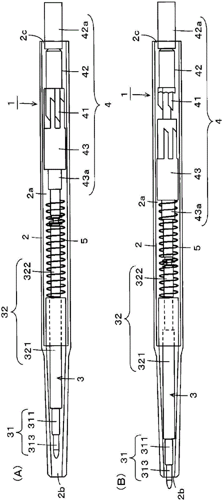
[0061] figure 1 The figure which shows the structural example of 1st Embodiment of the position indicator of this invention. The position indicator 1 of the first embodiment has a knock-type structure in which a core 3 for a position indicator is housed in a hollow portion 2a of a cylindrical frame 2, and a knock cam (knock cam) mechanism part 4 , access the tip of the position indicator core 3 from the opening 2b side at one end in the longitudinal direction of the frame body 2 .

[0062] figure 1 (A) shows the state in which the core 3 for the position indicator is housed in the hollow portion 2a of the frame body 2 as a whole, figure 1 (B) shows a state in which the tip side of the core 3 for a position indicator protrudes from the opening 2 b of the housing 2 by knocking the cam mechanism part 4 . In addition, in figure 1 In the example of , the housing 2 of the position indicator 1 is made of transparent synthetic resin, and the inside thereof is shown in a transp...

no. 2 Embodiment approach

[0106] The position indicator of the second embodiment is a modified example of the first embodiment. In the above-mentioned first embodiment, only one core for a position indicator is accommodated in the housing. In this second embodiment, a plurality of position indicator cores are accommodated in the housing, and one of the plurality of position indicator cores is selected by tapping the cam mechanism, and the selected position indicator core The front end of the nib portion of the object protrudes from the opening on the nib side of the frame for use.

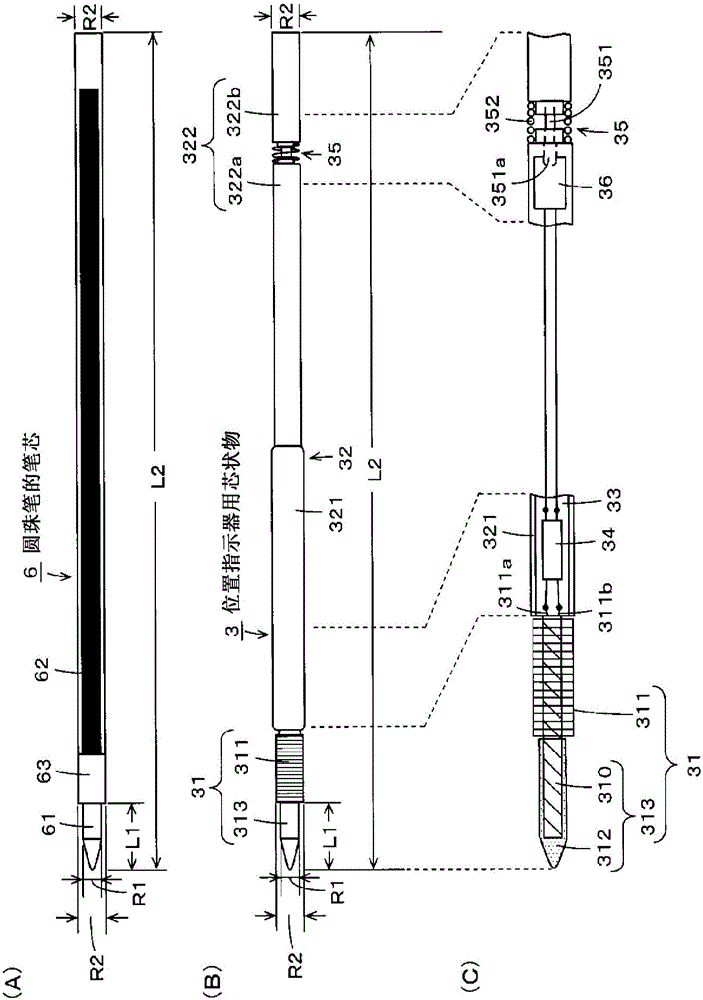
[0107] As described above, the position indicator core 3 of the position indicator 1 according to the first embodiment is configured to be compatible with the refill 6 of the ballpoint pen. As ballpoint pens on the market, there are multicolor ballpoint pens equipped with refills of different ink colors. This second embodiment provides a position indicator configured by accommodating the core 3 for a position indicator in...


PUM


Abstract

The purpose of the present invention is to reduce the thickness of a position indicator in which a resonance circuit comprising a coil and a capacitor receives a predetermined alternating current signal from a position detection device. The position indicator is provided with: a cylindrical case, which has an opening at the one end side which becomes the pen-tip side, and is closed at the other end side, in the axial direction thereof; and a cartridge for the position indicator, the cartridge being accommodated in a hollow section of the case. The cartridge for the position indicator comprises: a core body part in which the coil constituting the resonance circuit is partially wound around a rod-shaped magnetic core and a pen tip is formed such that a protective member covers at least the portion around which the coil of the magnetic core is not wound; and a cylindrical body part accommodating at least the capacitor constituting the resonance circuit.

Description

technical field [0001] The present invention relates to a position indicator and a cartridge for the position indicator, which are used together with a position detection device and are suitable, for example, as an electromagnetic induction method. Background technique [0002] The coordinate input device of the electromagnetic induction method is composed of a position detection device and a pen-shaped position indicator. The shaped position indicator has a resonant circuit composed of a coil, which is an example of an inductance element wound around a magnetic core, and a capacitor. [0003] Then, the position detection device supplies a transmission signal of a predetermined frequency to the loop coil of the sensor, and transmits it to the position indicator as electromagnetic energy. The resonant circuit of the position indicator is configured to have a resonant frequency corresponding to the frequency of the transmission signal, and stores electromagnetic energy based ...

Claims


Application Information

Patent Timeline
Patent Type & Authority Applications(China)
IPC IPC(8): G06F3/03G06F3/046
CPCG06F3/03545G06F3/0383G06F3/046G06F2203/04105G06F3/04162B43K7/005B43K24/16B43K27/12B43K29/00
Inventor 堀江利彦神山良二山下滋
Owner WACOM CO LTD
Features
  • R&D
  • Intellectual Property
  • Life Sciences
  • Materials
  • Tech Scout
  • Unparalleled Data Quality
  • Higher Quality Content
  • 60% Fewer Hallucinations
Learn More