
High-precision semi-automatic printer

A semi-automatic printing machine technology, applied in the electronic field, can solve the problems of high cost, large driving force, and low precision, and achieve the effects of saving floor space, improving accuracy, and facilitating operation

Inactive Publication Date: 2017-03-01
天津市叁盛缘电子有限公司
View PDF8 Cites 5 Cited by
  • Summary
  • Abstract
  • Description
  • Claims
  • Application Information

AI Technical Summary

Problems solved by technology

[0002] In the prior art, the solder paste printing equipment for printed circuit boards (PCB boards) includes a working platform and a screen frame. Board alignment is required. At present, solder paste printing equipment realizes board alignment by adjusting the position of the working platform in the X and Y directions. The volume and weight of the working platform are large, and the driving force required to drive the working platform is relatively large. The board is more difficult, the precision is lower, the speed is slower, the structure is complex, and the cost is higher. Therefore, there is a need for improvement in the prior art solder paste printing equipment

Method used


Image

  • High-precision semi-automatic printer
  • High-precision semi-automatic printer

Examples


Embodiment Construction

[0021] It should be noted that, in the case of no conflict, the embodiments of the present invention and the features in the embodiments can be combined with each other.

[0022] In describing the present invention, it should be understood that the terms "center", "longitudinal", "transverse", "upper", "lower", "front", "rear", "left", "right", " The orientations or positional relationships indicated by "vertical", "horizontal", "top", "bottom", "inner" and "outer" are based on the orientations or positional relationships shown in the drawings, and are only for the convenience of describing the present invention and Simplified descriptions, rather than indicating or implying that the device or element referred to must have a particular orientation, be constructed and operate in a particular orientation, and thus should not be construed as limiting the invention. In addition, the terms "first", "second", etc. are used for descriptive purposes only, and should not be understood ...


PUM


Abstract

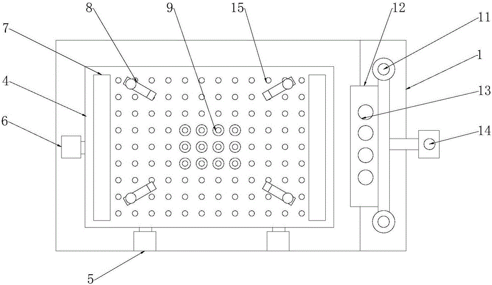
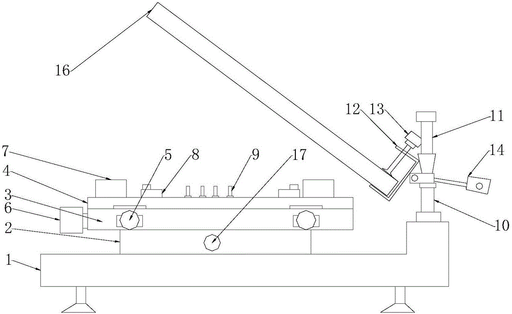
The invention provides a high-precision semi-automatic printer. The high-precision semi-automatic printer comprises a pedestal, a supporting platform, an adjusting table, a worktable, a fixing plate, positioning pins, fixing bolts, a pressing plate, a bracket and a fixing frame, wherein the supporting platform is fixed on the pedestal; the adjusting table is fixed on the supporting platform; the adjusting table is provided with an X-axis adjusting knob and a Y-axis adjusting knob; the worktable is positioned on the adjusting table; the surface of the worktable is provided with a plurality of positioning holes; the fixing plate is arranged on the worktable; a plurality of positioning pins are arranged at one side of the fixing plate; a plurality of fixing bolts are arranged at the sides of the positioning pins. The high-precision semi-automatic printer provided by the invention is simple and small in structure, capable of saving floor area, adjustable in speed and convenient to operate.

Description

technical field [0001] The invention belongs to the field of electronics, in particular to a high-precision semi-automatic printing machine. Background technique [0002] In the prior art, the solder paste printing equipment for printed circuit boards (PCB boards) includes a working platform and a screen frame. Board alignment is required. At present, solder paste printing equipment realizes board alignment by adjusting the position of the working platform in the X and Y directions. The volume and weight of the working platform are large, and the driving force required to drive the working platform is relatively large. The board is more difficult, the precision is lower, the speed is slower, the structure is complicated, and the cost is higher. Therefore, the prior art solder paste printing equipment needs to be improved. Contents of the invention [0003] In view of this, the present invention aims to provide a high-precision semi-automatic printing machine with simple s...

Claims


Application Information

Patent Timeline
Patent Type & Authority Applications(China)
IPC IPC(8): B41F15/08B41F15/16
CPCB41F15/0818B41F15/16
Inventor 左家明
Owner 天津市叁盛缘电子有限公司
Learn More