Terminal identifier allocation method, device and system

A terminal identification and distribution method technology, applied in wireless communication, network data management, electrical components, etc., can solve the problem of not being able to use the same C-RNTI, and achieve the effect of reducing signaling interaction and delay

Inactive Publication Date: 2017-03-01
ZTE CORP
View PDF0 Cites 10 Cited by
  • Summary
  • Abstract
  • Description
  • Claims
  • Application Information

AI Technical Summary

Problems solved by technology

[0006] In order to solve the above technical problems, the present invention provides a method, device and system for allocating terminal identifiers, which are used to solve the problem in the prior art that the UE cannot use the same C-RNTI before and after switching between different nodes

Method used


Image

  • Terminal identifier allocation method, device and system
  • Terminal identifier allocation method, device and system
  • Terminal identifier allocation method, device and system

Examples


Embodiment 1

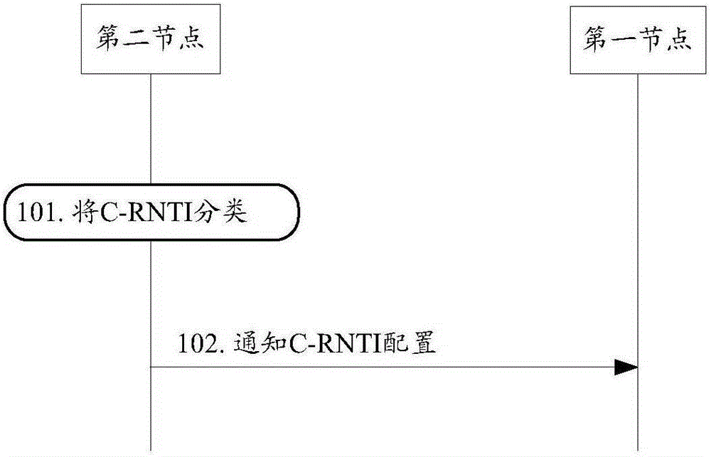
[0046] image 3 It is a flow chart of Embodiment 1 of the present invention. It should be noted that this embodiment only describes the process in which the second node notifies the first node of the configuration information of the C-RNTI, and the description of other irrelevant steps is omitted. Such as image 3 As shown, the specific description of this embodiment is as follows:

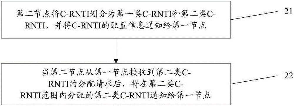
[0047] Step 101: The second node divides the C-RNTI into the first type of C-RNTI and the second type of C-RNTI; in this embodiment, the second node can modify the configuration information of the C-RNTI according to the following parameters: The number of UEs that have been accessed, the number of UEs requesting random access within a period of time, and the number of UEs that have not been assigned a C-RNTI among UEs requesting random access within a period of time;

[0048] Step 102: the second node notifies the first node of C-RNTI configuration information, where the C-RNTI configuration i...

Embodiment 2

[0051] Figure 4 It is a flow chart of Embodiment 2 of the present invention. It should be noted that this embodiment specifically describes the process of performing random access in UE initial access or connection re-establishment scenarios, omitting descriptions of steps unrelated to this embodiment, and, in this embodiment, UE No C-RNTI is allocated before access, and a C-RNTI needs to be obtained through random access. Such as Figure 4 As shown, the specific description of this embodiment is as follows:

[0052] Step 201: UE sends a random access preamble to the first node;

[0053] Specifically, the UE first selects a preamble (Preamble), and sends the preamble to the first node according to the random access resource information configured by the system;

[0054] Step 202: the first node sends a random access response message Msg2 to the UE;

[0055] Here, the random access response message Msg2 may include a preamble identifier corresponding to the random access ...

Embodiment 3

[0068] Figure 5 It is a flow chart of Embodiment 3 of the present invention. It should be noted that this embodiment specifically describes the process in which the target first node requests the target second node to allocate a second type of C-RNTI when the UE is handed over to the target first node and the target first node is connected to the target second node , the description of steps irrelevant to this embodiment is omitted, and, in this embodiment, the source base station may be any access network node that provides air interface access and the source base station is not connected to the target second node. Such as Figure 5 As shown, the specific description of this embodiment is as follows:

[0069] Step 301: the source base station sends a handover request message to the target first node, and the message includes handover preparation related messages;

[0070] Step 302: The target first node refers to the handover request message, and performs an admission dec...


PUM


Abstract

The invention discloses a terminal identifier allocation method, device and system. The terminal identifier allocation method comprises the steps that a first node receives configuration information of a second node for a C-RNTI (Cell-Radio Network Temporary Identifier), wherein the configuration information for the C-RNTI comprises the range of a first kind of C-RNTI and/or the range of a second kind of C-RNTI; and when the first node discovers that a source base station of UE is connected to the second node, the first node allows the UE to maintain the second kind of C-RNTI allocated by the second node to act as a C-RNTI of the UE to perform access. The terminal identifier allocation method, device and system disclosed by the invention are used for solving a problem that the UE in the prior art cannot use the same C-RNTI after being switched between different nodes.

Description

technical field [0001] The present invention relates to the field of wireless communication, in particular to a method, device and system for allocating terminal identifiers. Background technique [0002] Ultra Dense Network (UDN, Ultra Dense Network) is one of the most promising technical directions to improve the system capacity and user data rate of the fifth generation mobile communication technology (5G). In an ultra-dense network, low power nodes (LPN, Low Power Node), such as Remote Radio Unit (RRU, Radio Remote Unit) / Remote Radio Head (RRH, Remote Radio Head), pico base station (Pico eNB), home base station (Home eNB), relay nodes (Relay Node), etc., are densely deployed, and their density is even much higher than that of the small cell (small cell) enhancement technology in the fourth generation mobile communication technology (4G). The distance between low-power nodes is reduced and they can listen to each other. The distance between the low-power nodes and user ...

Claims


Application Information

Patent Timeline
Patent Type & Authority Applications(China)
IPC IPC(8): H04W8/26H04W36/00H04W74/00H04W74/08
CPCH04W72/04H04W8/26H04W36/0033H04W74/002H04W74/0833
Inventor 刘星
Owner ZTE CORP
Why Eureka
Try Eureka