Repair welding process used after thread blind hole depth difference exceeding

A threaded blind hole and repair welding technology, which is applied in the field of transformer production, can solve problems such as unrepairable deformation after welding, unusable flanges, waste of labor, material costs, etc., to reduce material costs and repair costs, and quickly restore use Effect

Active Publication Date: 2017-03-08
BAODING TIANWEI BAOBIAN ELECTRICAL
View PDF5 Cites 11 Cited by
  • Summary
  • Abstract
  • Description
  • Claims
  • Application Information

AI Technical Summary

Problems solved by technology

If the bottom hole is too deep, the reliability of the oil tightness (or air tightness) at the bottom of the threaded blind hole will be reduced, or it will directly cause oil (gas) leakage. Therefore, the flange (or other parts) with the problem of too deep bottom hole cannot be use
If the bottom hole is too deep, the repair method in the prior art is to re-drill and process the threaded holes after repairing all the screw holes; (or bottom plate and other parts) gas cutting or gas explosion, after removing it, replace it with a new one, and re-weld. There will be a lot of welding and post-welding shaping work during repair, and there will be a risk of irreparable post-welding deformation, which is very labor-intensive and time-consuming
At present, in the production of transformers, there are a large number of parts such as threaded blind hole flanges and bottom plates, and such quality problems will occur during processing. The existing technical repair methods need to waste a lot of labor and material costs, and there will be irreparable post-weld defects. Deformation risk, unable to meet production requirements

Method used


Image

  • Repair welding process used after thread blind hole depth difference exceeding
  • Repair welding process used after thread blind hole depth difference exceeding
  • Repair welding process used after thread blind hole depth difference exceeding

Examples


Embodiment Construction

[0019] The present invention will be further described through the embodiments below in conjunction with the accompanying drawings.

[0020] A repair welding process after the depth of a threaded blind hole is out of tolerance, comprising the following process steps:

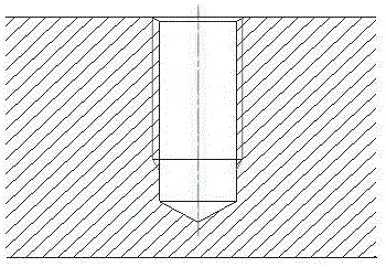
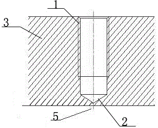
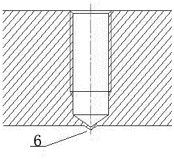
[0021] Process the threaded blind hole on the front of the workpiece 3. If the bottom hole of the threaded blind hole is too deep, analyze the situation of the bottom hole too deep, which can be divided into three types: A, top penetration 7, the hole depth of the threaded blind hole 1 is too large, and the bottom hole is tapered The cone tip of the end 2 penetrates the back of the workpiece 3; B, the protrusion 6, the hole depth of the threaded blind hole is too large, and the cone tip of the conical end of the bottom hole pushes up the back surface of the workpiece, but has not yet penetrated the workpiece; C. Too thin 5. Although the hole depth of the threaded blind hole is too large, the tapered end of the b...


PUM


Abstract

The invention relates to a repair welding process used after thread blind hole depth difference exceeding, and belongs to the technical field of transformer production. According to the technical scheme, as for through-top, protruding and too-thin thread blind holes, a pointed cone (4) is used for knocking through-top, protruding and too-thin parts at the back face of workpieces, the knocking force enables the parts to form conical grooves, and conical tips of the conical grooves cannot exceed conical ends of bottom holes; and the thread blind holes are filled with copper bars or asbestos cords, repair welding is carried out at the conical grooves, the repair welding thickness is slightly larger than that of the surfaces of the back faces of the workpieces, and then rubdown is carried out. The repair welding process has the beneficial effects that repairing after the bottom holes of the thread blind holes of the parts are too deep is achieved, the parts can be rapidly desterilized while the original reliable sealing thickness of the parts is recovered, the material cost and the maintaining cost for flange replacement are reduced, and the repair welding process is particularly suitable for the transformer production process.

Description

technical field [0001] The invention relates to a repair welding process after the depth of a threaded blind hole is out of tolerance, and belongs to the technical field of transformer production. Background technique [0002] Many workpieces such as flanges and bottom plates with threaded blind holes are used in the manufacture of transformer oil tanks. For the form of threaded blind holes, see the attached figure 1 . In the process of processing, sometimes there is a deviation in the control of the depth of the bottom hole. If the bottom hole is too deep, there will be quality problems such as too thin steel plate at the bottom of the bottom hole, bulging at the bottom of the bottom hole, and penetration at the bottom of the bottom hole. For details, see the attached figure 2 hint. If the bottom hole is too deep, the reliability of the oil tightness (or air tightness) at the bottom of the threaded blind hole will be reduced, or it will directly cause oil (gas) leakage. ...

Claims


Application Information

Patent Timeline
Patent Type & Authority Applications(China)
IPC IPC(8): B23P6/00
CPCB23P6/00
Inventor 李崇张海燕曹伟龙崔少华杨立军葛惠卿
Owner BAODING TIANWEI BAOBIAN ELECTRICAL
Why Eureka
Try Eureka