
Transfer Case Having A Traction Element Offset Mechanism

A technology of traction mechanism and transmission device, which is applied in the field of transfer case, can solve the problems of component cost and consumption, and achieve the effects of structural and economic optimization, structural space optimization, and component optimization

Inactive Publication Date: 2017-03-08
MAGNA POWERTRAIN AG & CO KG
View PDF12 Cites 1 Cited by
  • Summary
  • Abstract
  • Description
  • Claims
  • Application Information

AI Technical Summary

Problems solved by technology

These loads must always be taken into account when designing the components and often result in increased component and thus cost outlays

Method used


Image

  • Transfer Case Having A Traction Element Offset Mechanism
  • Transfer Case Having A Traction Element Offset Mechanism
  • Transfer Case Having A Traction Element Offset Mechanism

Examples


Embodiment Construction

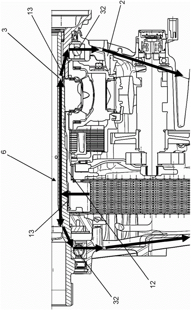
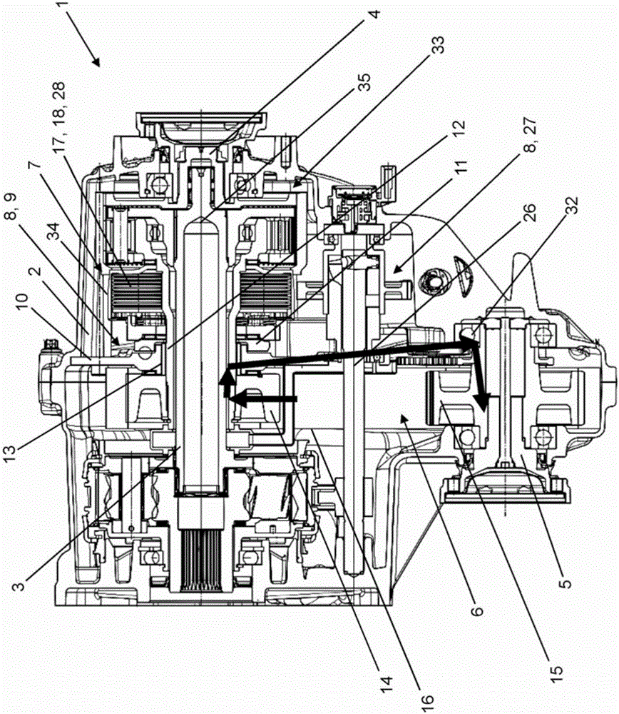
[0053] figure 1 A detailed view of a longitudinal section through a transfer case 1 according to the prior art is shown.

[0054] To describe components, in figure 1 In the transfer case 1 of the prior art shown in , the reference numerals corresponding to the components of the present invention are used.

[0055] According to the existing technology in figure 1 The transfer case shown in , which is not described in detail below, is only used to illustrate how the traction forces of the traction means 16 of the traction means offset transmission 6 are supported in a known manner.

[0056] exist figure 1 The transfer case 1 shown in includes an input shaft 3 and an offset transmission 6 .

[0057] The offset transmission 6 is used to bridge the offset between the input shaft 3 and the second output shaft 5 (not shown).

[0058] The offset drive 6 is designed as a chain drive with a first traction mechanism disk 14 and a second traction mechanism disk 15 (not shown) each in...


PUM


Abstract

A transfer case for a motor vehicle, comprising a housing, an input shaft, a first output shaft, which is arranged substantially coaxially with the input shaft and is operatively drive-connected to the input shaft, a second output shaft, which is arranged offset in relation to the input shaft and which is or can be operatively drive-connected to the input shaft via an offset mechanism, in the form of a flexible traction drive, and via a clutch unit, an actuator unit which serves for actuating the clutch unit, the actuator unit comprising a ramp mechanism having a first ramp disk fixed to the housing and a second, axially displaceable ramp disk, and a carrier shaft which is embodied as a hollow shaft and which at least partially encloses the input shaft, the carrier shaft being rotatably supported on the first ramp disk via a radial bearing.

Description

technical field [0001] The invention relates to a transfer case for a motor vehicle with a traction mechanism offset transmission. Background technique [0002] Transfer cases are used in particular in motor vehicles with all-wheel drive. The transfer case is used to distribute the torque generated by the driving engine and provided on the input shaft of the transfer case to at least two output shafts of the transfer case, the at least two output shafts are respectively driven with the axles of the motor vehicle connect. [0003] Along the flow of force from the drive engine of the motor vehicle to the driven axles of the motor vehicle, a transfer case is usually arranged downstream of the main transmission of the drive engine for converting the torque produced by the drive engine. [0004] Depending on the design of the transfer case, a distinction is basically made between a differential-controlled transfer case and a clutch-controlled transfer case. [0005] In differe...

Claims


Application Information

Patent Timeline
IPC IPC(8): B60K17/346B60K23/08
CPCB60K17/3462B60K23/0808B60K2023/0816B60K2023/0825B60K17/346B60K23/08B60K17/342B60K17/02
Inventor 马丁·施托克
Owner MAGNA POWERTRAIN AG & CO KG
Learn More