Three-dimensional seismic isolation support with vertical initial stiffness capable of being preset
A seismic isolation bearing and initial stiffness technology, which is applied in the direction of earthquake resistance, building components, building structure, etc., can solve the problems of reducing the cost of seismic isolation, shortening the effective working length of the spring, unable to stretch and consume energy, and achieve buffering. Effects of tensile and compressive shocks, reduced wind and shock costs, and reduced risk of overturning
- Summary
- Abstract
- Description
- Claims
- Application Information
AI Technical Summary
Problems solved by technology
Method used
Image
Examples
example 1
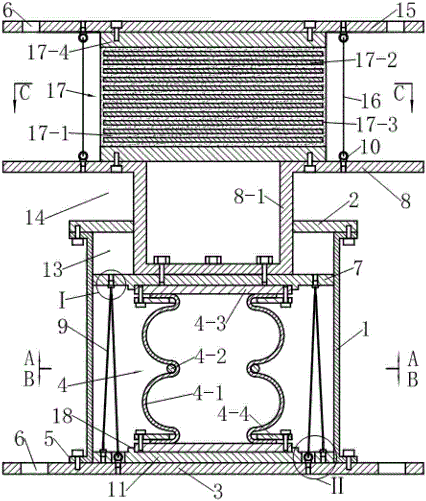
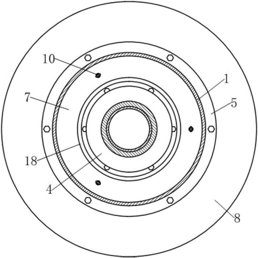
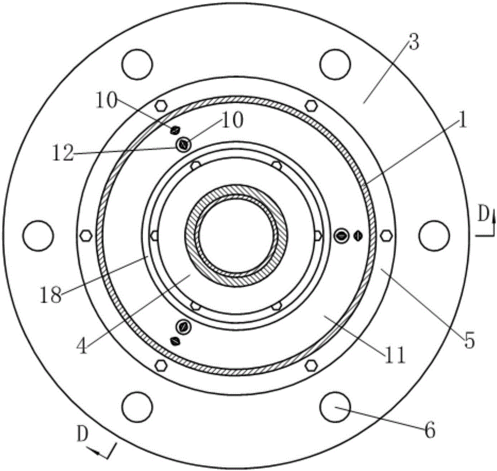
[0041] see figure 1 , the three-dimensional seismic isolation bearing in this example is composed of laminated rubber isolation bearings and vertical isolation bearings connected in series up and down.
[0042] see figure 1 with Figure 4 , the laminated rubber shock-isolation bearing includes an upper connection plate 15, a lower connection plate 8, a laminated rubber pad 17 clamped between the upper and lower connection plates and six tensile steel wire ropes 16; wherein, the upper connection Both the plate 15 and the lower connecting plate 8 are disc-shaped, and the edge of the upper connecting plate 15 is provided with mounting holes 6; the main body of the laminated rubber pad 17 is alternately laminated by a layer of rubber 17-1 and a layer of steel plate 17-2. It is formed by molding vulcanization after being combined, and a rubber protection layer 17-3 is naturally formed around it during the molding vulcanization process. The upper and lower ends of the main body...
example 2
[0057] see Figure 7-12 , on the basis of example 1, this example has mainly carried out the following improvements: (1) increasing the number of preloaded steel wire ropes 9 from three to four; (2) replacing the eyebolt 10 as the direction changing element of the steel wire rope with a U-shaped member 19; (3) replace the eye screw 10 that fixes the other end of the preloaded wire rope 9 with a wire rope self-locking anchor 20; (4) thicken the middle part of the base 3 and bulge upward to form an inverted washbasin shape, so as to facilitate the installation of the wire rope Self-locking anchor 20; (5) correspondingly change described back pressure device to:
[0058] The back pressure device consists of four preloaded steel wire ropes 9, four U-shaped components 19 as wire rope direction changing elements, a floating back pressure steel plate 11, four eyebolts 10 for fixing one end of the preloaded steel wire rope 9 and four fixed The steel wire rope self-locking anchor 20 a...
example 3
[0067] see Figures 13 to 16 , this example has mainly carried out following improvement on the basis of example 2: (1) replace the U-shaped member 19 as wire rope changing element with fixed pulley 21; (2) correspondingly change described back pressure device as:
[0068] The back pressure device consists of six preloaded steel wire ropes 9, six fixed pulleys 20 as steel wire rope direction changing elements, a floating back pressure steel plate 11, six fixed preloaded steel wire ropes 9 with ring screws 10 at one end and six fixed preloaded steel wire ropes. 9. The steel wire rope self-locking anchor 20 at the other end is formed. in,
[0069] The floating anti-pressure steel plate 11 is arranged between the rubber air spring 4 and the base 3, and is in dynamic cooperation with the guide sleeve 1;
[0070] Six fixed pulleys 21 as steel wire rope direction changing elements are fixed symmetrically around the axis of the guide sleeve 1 on the lower surface of the driving pla...
PUM
 Abstract
Description
Claims
Application Information
 - R&D
- Intellectual Property
- Life Sciences
- Materials
- Tech Scout
- Unparalleled Data Quality
- Higher Quality Content
- 60% Fewer Hallucinations
Browse by: Latest US Patents, China's latest patents, Technical Efficacy Thesaurus, Application Domain, Technology Topic, Popular Technical Reports.
© 2025 PatSnap. All rights reserved.Legal|Privacy policy|Modern Slavery Act Transparency Statement|Sitemap|About US| Contact US: help@patsnap.com


