Horizontal compressor and temperature adjusting device

A compressor and horizontal technology, applied in the field of horizontal compressors and temperature control equipment, can solve problems such as pressure drop, unsealable, poor sealing of sliding vanes and cylinders, etc.

Active Publication Date: 2017-03-08
GREE ELECTRIC APPLIANCES INC OF ZHUHAI +1
View PDF8 Cites 6 Cited by
  • Summary
  • Abstract
  • Description
  • Claims
  • Application Information

AI Technical Summary

Problems solved by technology

[0004] The necessary condition for the formation and sealing of the compression chamber is that the sliding vane in the rotor is against the cylinder wall, and at the moment the compressor is started, the sliding vane is thrown out of the sliding vane slot quick

Method used


Image

  • Horizontal compressor and temperature adjusting device
  • Horizontal compressor and temperature adjusting device
  • Horizontal compressor and temperature adjusting device

Examples


Example Embodiment

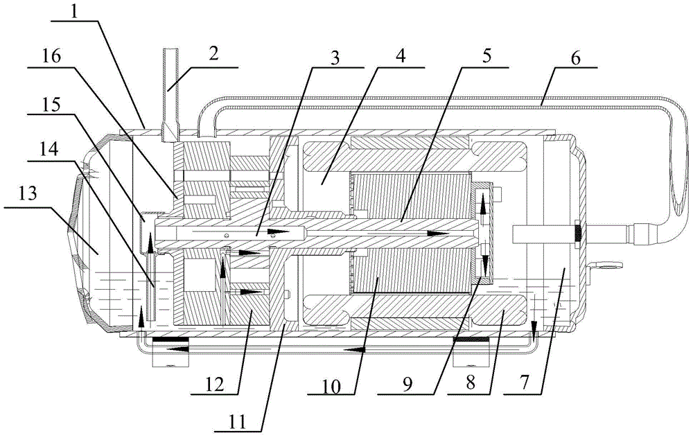
[0035] One of the cores of the present invention is to provide a horizontal compressor to ensure that the sliding vane can be extended smoothly when the compressor is started, and the sliding vane and the cylinder can maintain a proper adhesion force during normal operation, thereby improving compression The reliability of the machine.

[0036] Another core of the present invention is to provide a temperature regulating device with the above-mentioned horizontal compressor.

[0037] In order to enable those skilled in the art to better understand the solution of the present invention, the present invention will be further described in detail below with reference to the accompanying drawings and specific embodiments.

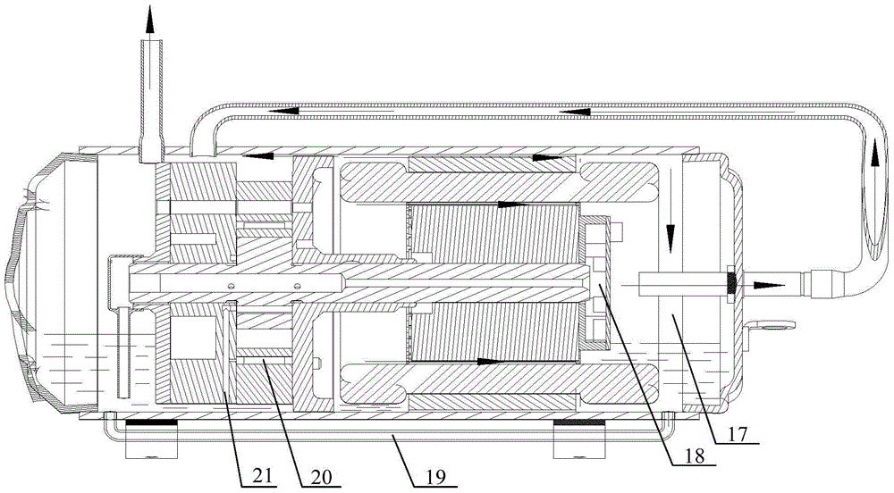
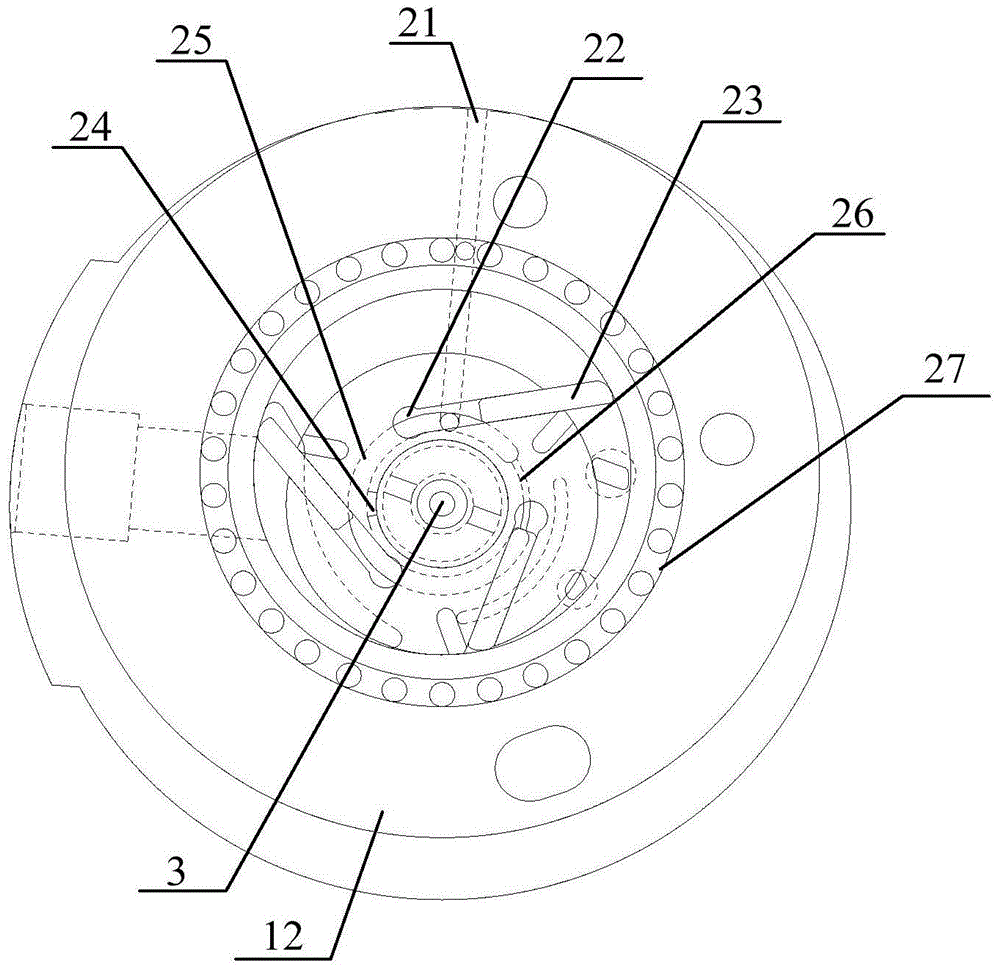
[0038] Please refer to Figure 1 to Figure 4 , figure 1 Is a schematic cross-sectional view of a horizontal compressor showing the flow direction of lubricating oil in an embodiment of the present invention, figure 2 Is a schematic cross-sectional view of a horizontal...


PUM


Abstract

The invention relates to a horizontal compressor which comprises a shell, a lower flange, an air cylinder, an upper flange and a motor. The lower flange, the air cylinder, the upper flange and the motor are sequentially arranged in the shell. An oil storage cavity is formed by the lower flange and the shell. A rotor is rotationally arranged in the air cylinder through a main shaft. The horizontal compressor further comprises a center oil hole penetrating the main shaft, a radial hole formed in the main shaft and communicating with the center oil hole, an oiling pipe fixedly connected to the end, located in the oil storage cavity, of the main shaft and communicating with the center oil hole, a lower flange back pressure groove formed in the lower flange and communicating with a sliding piece installation groove of the rotor, a groove for communicating the lower flange back pressure groove and the radial hole of the main shaft, an exhaust cavity communicating with an exhaust hole of the air cylinder and the center oil hole of the main shaft, and a fan installed at the other end of the fan, wherein the bottom end of the oiling pipe is close to the bottom of the oil storage cavity. According to the horizontal compressor, smooth stretching-out of a sliding piece during starting of the compressor and attachment between the sliding piece and the air cylinder during normal running of the compressor are effectively ensured. The invention further discloses a temperature adjusting device comprising the horizontal compressor.

Description

technical field [0001] The invention relates to the technical field of compressor manufacturing, in particular to a horizontal compressor and temperature regulating equipment. Background technique [0002] When the horizontal compressor is installed, the compressor is placed horizontally or close to the horizontal, so that the installation height of the horizontal compressor is greatly reduced, which can effectively save the installation space. It is widely used in equipment and vehicle air conditioning. [0003] The sliding vane horizontal compressor usually includes a cylinder, a rotor that cooperates with the cylinder, and a sliding vane set in the rotor. The cylinders are offset so that the space inside the cylinder is separated to form multiple independent compression chambers. During the rotation process, the volume of a part of the compression chamber gradually decreases to compress the gas, while the volume of a part of the compression chamber increases to complete...

Claims


Application Information

Patent Timeline
IPC IPC(8): F04C18/344F04C29/04F04C29/02
Inventor 杨国蟒徐嘉任丽萍万鹏凯罗发游吴飞
Owner GREE ELECTRIC APPLIANCES INC OF ZHUHAI
Why Eureka
Try Eureka