
Vibration-type condensing tube

A condensing tube and vibrating technology, applied in heat exchange equipment, lighting and heating equipment, heat transfer modification, etc., can solve the problems of poor convection and heat exchange performance, and can not realize the heat exchange process, etc., to achieve good cooling effect Effect

Inactive Publication Date: 2017-03-08
平湖迈柯罗新材料有限公司
View PDF8 Cites 0 Cited by
  • Summary
  • Abstract
  • Description
  • Claims
  • Application Information

AI Technical Summary

Problems solved by technology

[0003] However, due to the characteristics of the fluid itself, the flow between fluids is not affected by external forces, and its convection and heat exchange performance is not good, and the maximum heat exchange process cannot be realized.

Method used


Image

  • Vibration-type condensing tube
  • Vibration-type condensing tube

Examples


Embodiment Construction

[0016] The present invention will be further described below with reference to the accompanying drawings.

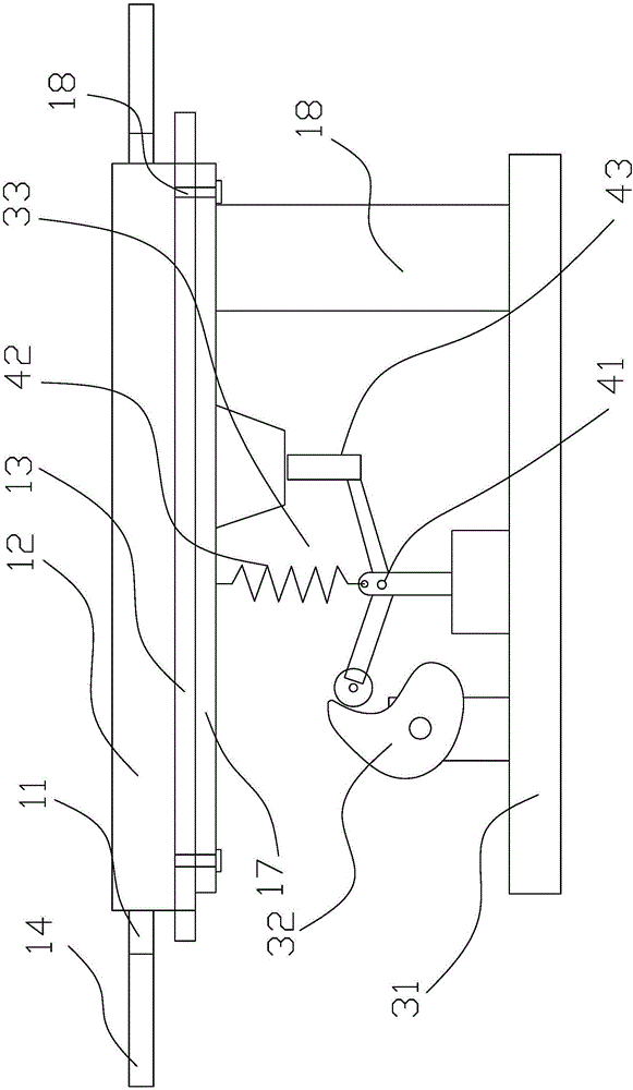
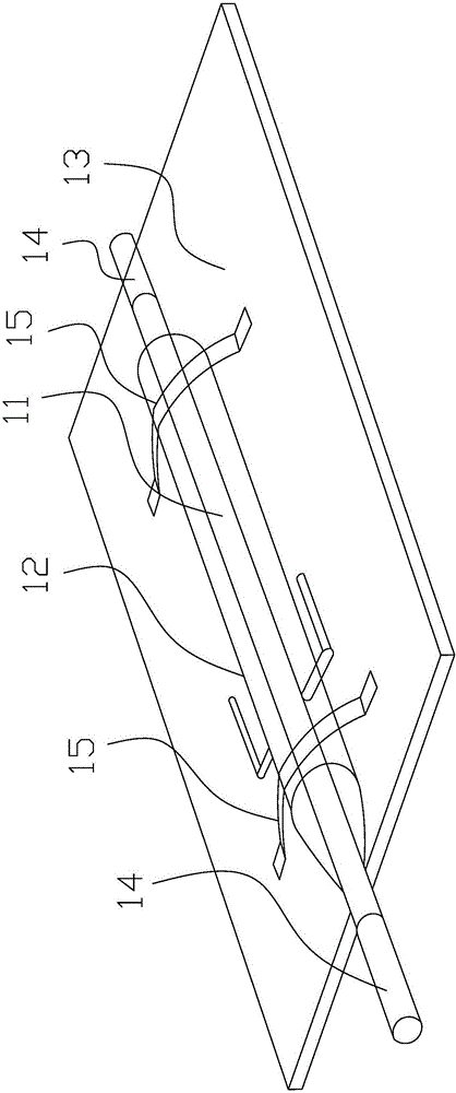
[0017] Reference attached figure 1 and figure 2 .

[0018] The present invention comprises a condensation tube 1 and a vibrator 2, the condensation tube includes an inner tube 11 and an outer tube 12, a base plate 13 is arranged under the outer tube 12, the base plate 13 is fixed with the outer tube 12, and the base plate 13 is connected with the outer tube 12. vibrator 3 connection;

[0019] Described vibrator 3 comprises base 31, eccentric mechanism 32, transmission mechanism, vibration mechanism 33 and motor, figure 1 The motor is not shown in the figure, and the motor is coaxially connected with the eccentric mechanism 32 to realize driving. The vibrating mechanism 33 is connected with the base plate 13, and the base plate vibrates together with the vibrating mechanism, so as to realize the simultaneous vibration of the outer tube and the inner tube on the base ...


PUM


Abstract

The invention provides a vibration-type condensing tube for realizing maximum flowing among fluids and then realizing that all the fluids can be furthest close to an inner tube to carry out heat exchange with a refrigerant, thus realizing cooling with the highest efficiency. The vibration-type condensing tube comprises a condensing tube and a vibrator, wherein the condensing tube comprises the inner tube and an outer tube, a base plate is arranged below the outer tube, and the base plate is fixed to the outer tube and connected with the vibrator; and the vibrator comprises a base, an eccentric mechanism, a transmission mechanism, a vibration mechanism and a motor, the vibration mechanism is connected with the base plate, and the base plate and the vibration mechanism vibrate together to realize simultaneous vibration of the outer tube and the inner tube on the base plate. The condensing tube provided by the invention realizes convection between the refrigerant and the fluid in the inner tube, and the maximum heat exchange through connection with the vibrator, thus achieving a better cooling effect.

Description

technical field [0001] The invention relates to a condensation pipe, in particular to a condensation pipe connected with a vibrator to realize vibration. Background technique [0002] The condensing tube is commonly used as a cooling device for lowering the temperature and adjusting the temperature. The cooling is realized through the heat exchange between the refrigerant in the outer tube and the working medium flowing in the inner tube. Due to the fluidity of the working fluid, the heat exchange is firstly the fluid in contact with the inner tube wall, and then the heat exchange between the inner tube and the outer tube, and the heat exchange between the fluids in the inner tube. [0003] However, due to the characteristics of the fluid itself, the flow between fluids is not affected by external forces, and its convection and heat exchange performance is not good, and the maximum heat exchange process cannot be realized. Contents of the invention [0004] The technical ...

Claims


Application Information

Patent Timeline
Patent Type & Authority Applications(China)
IPC IPC(8): F28F13/10
CPCF28F13/10F28F2250/08
Inventor 贾震雨毛利萌吴列平
Owner 平湖迈柯罗新材料有限公司
Learn More