Convection type heat dissipation power cabinet

A power cabinet and cabinet technology, applied in the field of convection cooling power cabinets, can solve the problems of unfavorable power cabinet high-power operation, slow heat dissipation, and large heat generation of power cabinets, and achieve excellent heat dissipation effect.

Inactive Publication Date: 2017-09-22
李聪
View PDF0 Cites 2 Cited by
  • Summary
  • Abstract
  • Description
  • Claims
  • Application Information

AI Technical Summary

Problems solved by technology

[0002] Power cabinets are widely used in major power companies, photovoltaic power plants, thermal power plants, hydropower plants, etc. in the country. Power cabinets are common equipment. For the current power cabinets, they are mainly composed of a roughly Power equipment that works continuously and has a large current, so the internal heat of the power cabinet is relatively large, and it is necessary to set up a heat dissipation area on the surface of the shell. The current heat dissipation area is composed of strip-shaped louvers that are symmetrically opened on both sides of the power cabinet shell. , the heat dissipation is slow, which is not conducive to the high-power operation of the power cabinet

Method used


Image

  • Convection type heat dissipation power cabinet
  • Convection type heat dissipation power cabinet

Examples


Embodiment 1

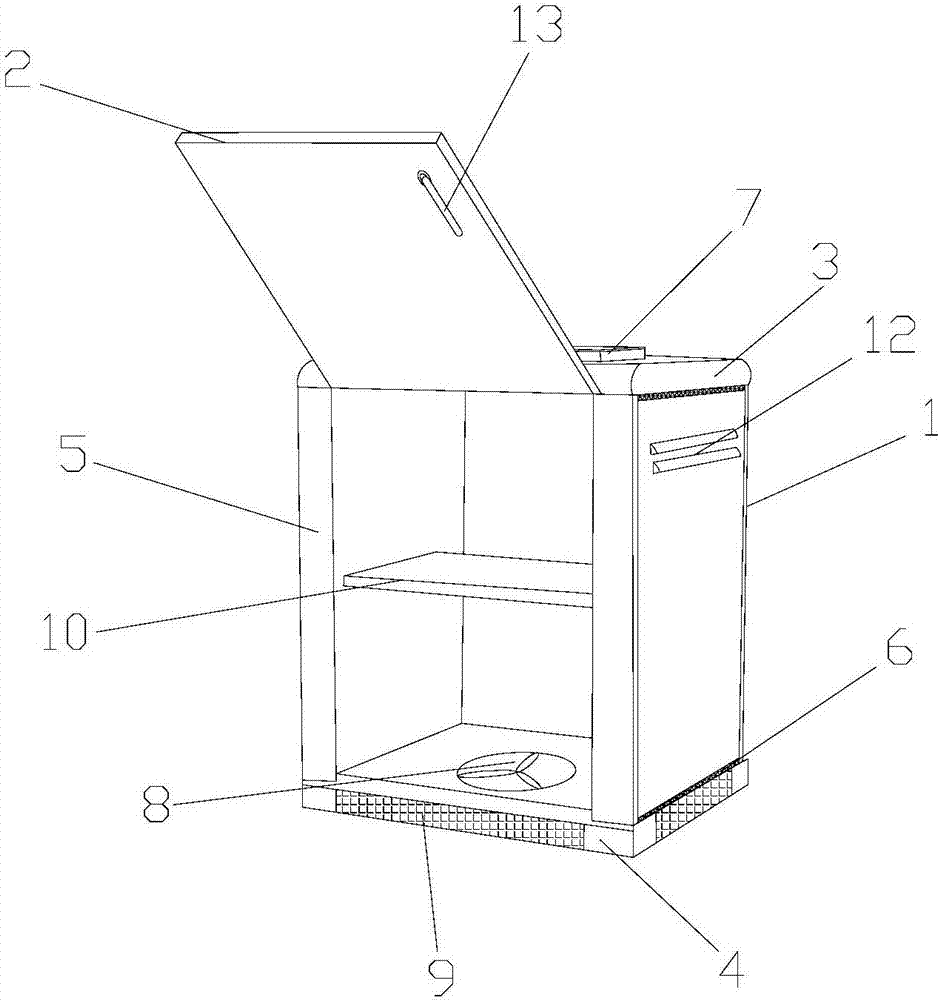
[0025] Such as Figure 1-2 As shown, a convection heat dissipation power cabinet includes a cabinet body 1 and a cabinet door 2, and the cabinet body 1 includes an upper cover 3, a lower cover 4 and side panels 5, and the upper cover 3 and the lower cover 4 are both Self-tapping screws (not shown) are installed, and the self-tapping screws are threadedly connected with the side plate 5, and the self-tapping screws are all embedded in the upper cover 3 and the lower cover 4, and the upper cover 3 and the lower cover 4 are connected with the lower cover 4. Conductive cloth pads 6 are arranged between the side plates, the upper cover 3 is provided with a blower 7, the lower cover 4 is hollow, the lower cover 4 is equipped with an exhaust fan 8, and the exhaust fan 8 To be embedded in the lower cover 4, the lower cover 4 is provided with an air vent 9, the side plate 5 is provided with an aluminum veneer 10, and the aluminum veneer 10 is provided with a vent (not shown) , a magne...

Embodiment 2

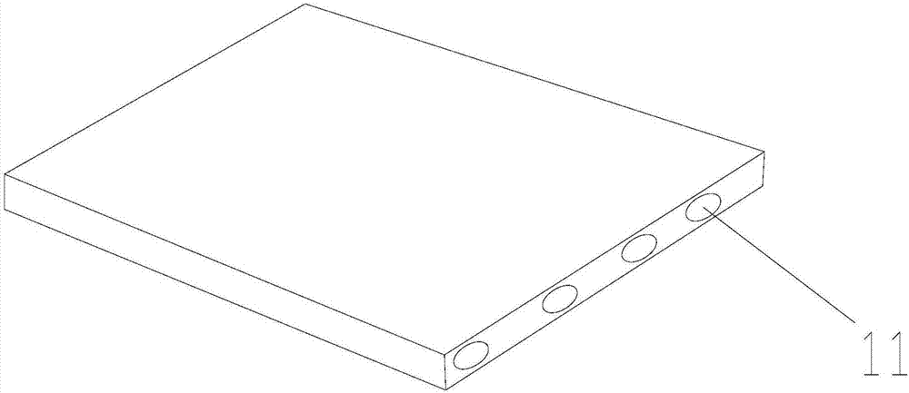
[0040] Such as Figure 1-2 As shown, a convection heat dissipation power cabinet includes a cabinet body 1 and a cabinet door 2, and the cabinet body 1 includes an upper cover 3, a lower cover 4 and side panels 5, and the upper cover 3 and the lower cover 4 are both Self-tapping screws (not shown) are installed, and the self-tapping screws are threadedly connected with the side plate 5, and the self-tapping screws are embedded in the upper cover 3 and the lower cover 4, and the upper cover 3 and the lower cover 4 are connected with the lower cover 4. Conductive cloth pads 6 are arranged between the side plates, the upper cover 3 is provided with a blower 7, the lower cover 4 is hollow, the lower cover 4 is equipped with an exhaust fan 8, and the exhaust fan 8 To be embedded in the lower cover 4, the lower cover 4 is provided with an air vent 9, the side plate 5 is provided with an aluminum veneer 10, and the aluminum veneer 10 is provided with a vent (not shown) , a magnet 11...

Embodiment 3

[0055] Such as Figure 1-2 As shown, a convection heat dissipation power cabinet includes a cabinet body 1 and a cabinet door 2, and the cabinet body 1 includes an upper cover 3, a lower cover 4 and side panels 5, and the upper cover 3 and the lower cover 4 are both Self-tapping screws (not shown) are installed, and the self-tapping screws are threadedly connected with the side plate 5, and the self-tapping screws are all embedded in the upper cover 3 and the lower cover 4, and the upper cover 3 and the lower cover 4 are connected with the lower cover 4. Conductive cloth pads 6 are arranged between the side plates, the upper cover 3 is provided with a blower 7, the lower cover 4 is hollow, the lower cover 4 is equipped with an exhaust fan 8, and the exhaust fan 8 To be embedded in the lower cover 4, the lower cover 4 is provided with an air vent 9, the side plate 5 is provided with an aluminum veneer 10, and the aluminum veneer 10 is provided with a vent (not shown) , a magne...


PUM


Abstract

The invention discloses a convection type heat dissipation power cabinet. The convection type heat dissipation power cabinet comprises a cabinet body and a cabinet door, wherein the cabinet body comprises an upper cover, a lower cover and a side plate, wherein self-tapping screws are arranged on the upper cover and the lower cover, are in threaded connection with the side plate and are embedded onto the upper cover and the lower cover, conductive fabric gaskets are arranged between the upper cover and the side plate and between the lower cover and the side plate, an air blower is arranged on the upper cover, the lower cover is hollow, an exhaust fan is arranged on the lower cover and is embedded into the lower cover, exhaust holes are formed in the lower cover, an aluminum single plate is arranged on the side plate, ventilation holes are formed in the aluminum single plate, magnets are arranged on the aluminum single plate, heat dissipation shutters are arranged on the side plate, a vacuum suction disc is arranged on the cabinet door, and a thermometer is arranged on the vacuum suction disc and is embedded into the vacuum suction disc. The convection type heat dissipation power cabinet has excellent heat dissipation performance.

Description

technical field [0001] The invention relates to a convection heat dissipation power cabinet. Background technique [0002] Power cabinets are widely used in major power companies, photovoltaic power plants, thermal power plants, hydropower plants, etc. in the country. Power cabinets are common equipment. For the current power cabinets, they are mainly composed of a roughly Power equipment that works continuously and has a large current, so the internal heat of the power cabinet is relatively large, and it is necessary to set up a heat dissipation area on the surface of the shell. The current heat dissipation area is composed of strip louvers that are symmetrically opened on both sides of the power cabinet shell. , the heat dissipation is slow, which is not conducive to the high-power operation of the power cabinet. Contents of the invention [0003] The technical problem to be solved by the present invention is to provide a convection heat dissipation power cabinet with e...

Claims


Application Information

Patent Timeline
Patent Type & Authority Applications(China)
IPC IPC(8): H02B1/56H02B3/00C22C32/00C22C21/14C09D201/00C09D7/12
CPCC08K2003/2296C08L2205/03C09D167/00C09D201/00C22C21/14C22C32/0005H02B1/30H02B1/301H02B1/306H02B1/38H02B1/565H02B3/00C08L23/06C08K13/04C08K7/06C08K5/09C08K3/22C08K3/04C08K3/34C08K5/42C08L101/00
Inventor 李聪
Owner 李聪
Why Eureka
Try Eureka