
Modular generator

A generator and magnet technology, applied in the field of modular generators, can solve the problems of large generator loss, output power reduction, and difficult heat diffusion, etc., and achieve the effect of reduced volume, large output power, and favorable heat diffusion

Active Publication Date: 2016-04-27
XINJIANG XINYU KANGJIAN BIOTECH CO LTD
View PDF15 Cites 2 Cited by
  • Summary
  • Abstract
  • Description
  • Claims
  • Application Information

AI Technical Summary

Problems solved by technology

[0002] Currently on the market, the structure of the generator is provided with a stator and a rotor that can interact in the casing, and the transmission shaft is arranged on the casing and fixed with the rotor. When the external mechanical power drives the transmission shaft to rotate, that is, at the same time The rotor is driven to rotate, and the rotor and the oppositely arranged stator can generate electric energy and output it after the action of the magnetic force lines, but the loss of the traditional generator is large and the output is small. If a certain efficiency is required, it must have a certain volume, so it takes up space. Large and the heat generated inside is not easy to spread, resulting in a significant reduction in output power

Method used


Image

  • Modular generator
  • Modular generator
  • Modular generator

Examples


Embodiment Construction

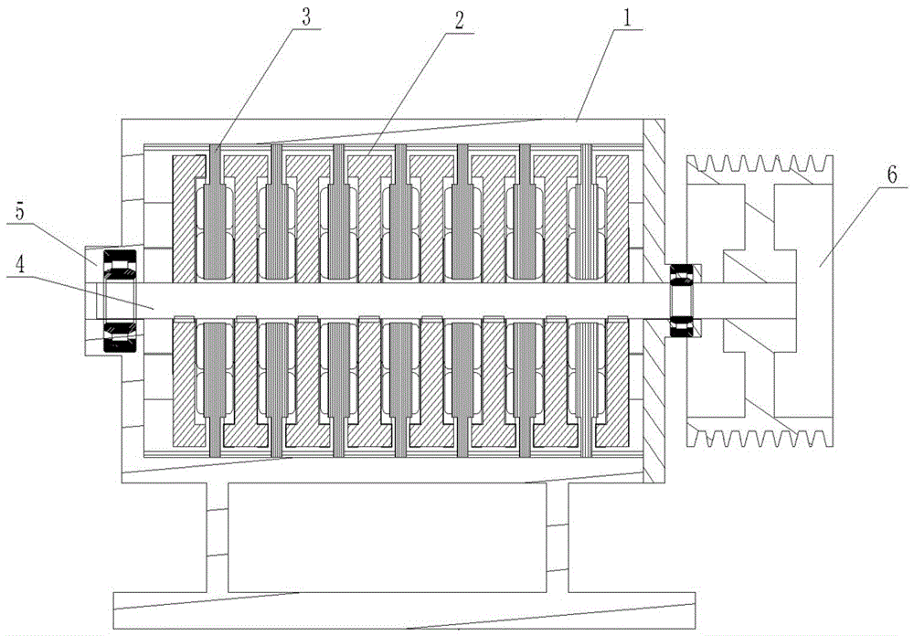
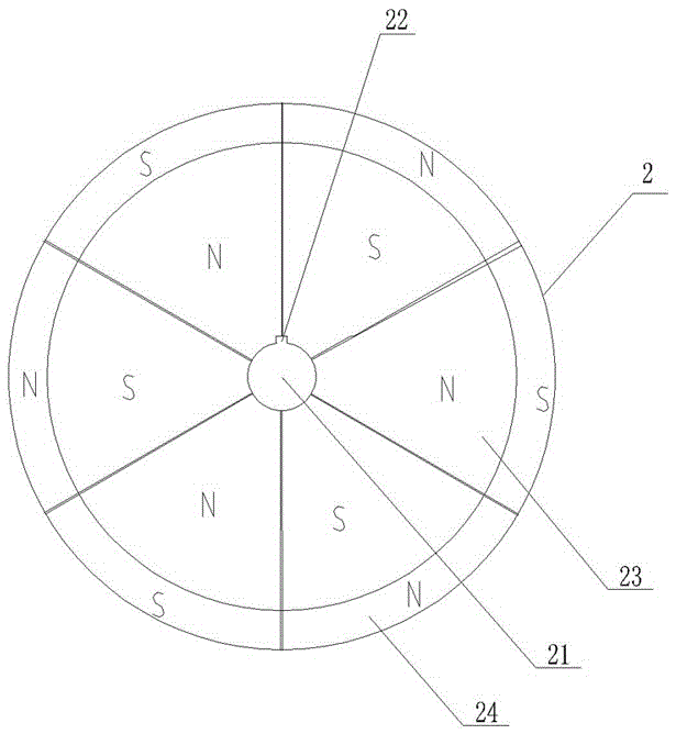
[0018] Refer to attached figure 1 And attached figure 2 , a modular generator, including a housing 1, at least two magnet rotors 2, at least one coil stator 3 and a drive shaft 4, the inside of the housing 1 is hollow and cylindrical, and the surface of the housing 1 is provided with vent holes, which help for the diffusion of heat. Both ends of the cylindrical housing 1 are respectively provided with shaft seats 5. In this embodiment, the magnet rotor 2 is provided with eight pieces, and the coil stator 3 is provided with seven pieces, that is, the two sides of the coil stator 3 are respectively provided with A magnet rotor 2, the combination of the magnet rotor 2 and the coil stator 3 is installed in the housing 1, the transmission shaft 4 runs through the housing 1, the combination of the magnet rotor 2 and the coil stator 3 and the pulley 6, and the transmission shaft 4 and the magnet rotor 2 are mutually Combined with the fixation, the belt pulley 6 drives the transmis...


PUM


Abstract

The invention relates to a modular generator which comprises a shell, at least two magnet rotors, at least one coil stator and a transmission shaft. The modular generator is characterized in that the centers of the magnet rotors are provided with shaft holes which are used for enabling the transmission shaft to pass through and are driven to rotate by the transmission shaft; each magnet rotor is uniformly provided with the even number of units in the peripheral direction; a magnet is arranged in each unit; the magnets in each two adjacent units are different in polarity; the magnets in the opposite units between each two adjacent magnet rotors are different in polarity; each coil stator is uniformly provided with a silicon steel sheets of which the number is the same with that of the units of each magnet rotor in the peripheral direction; the silicon steel sheets are radially mounted on a ring-shaped bracket; the ring-shaped bracket is uniformly wound with a coil; the coil is separated by the silicon steel sheets; the magnet rotors and the coil stators are alternately arranged and fixed on the transmission shaft; input power is low, and output power is high; a load is increased, and the input power is not increased, but is reduced; and the coil stators and the magnet rotors are modularized, so that a volume is reduced.

Description

technical field [0001] The invention relates to a modularized generator which converts mechanical energy into electric energy by modularizing a coil stator and a magnet rotor and installing them in a casing. Background technique [0002] Currently on the market, the structure of the generator is provided with a stator and a rotor that can interact in the casing, and the transmission shaft is arranged on the casing and fixed with the rotor. When the external mechanical power drives the transmission shaft to rotate, that is, at the same time The rotor is driven to rotate, and the rotor and the oppositely arranged stator can generate electric energy and output it after the action of the magnetic force lines, but the loss of the traditional generator is large and the output is small. If a certain efficiency is required, it must have a certain volume, so it takes up space. Large and the heat generated inside is not easy to spread, resulting in a significant reduction in output po...

Claims


Application Information

Patent Timeline
Patent Type & Authority Applications(China)
IPC IPC(8): H02K16/00H02K21/24
CPCH02K16/00H02K21/24
Inventor 李兰儒
Owner XINJIANG XINYU KANGJIAN BIOTECH CO LTD
Learn More