Ultraviolet photochemical reactor device based on continuous flow technology

A photochemical reaction and reactor technology, applied in the field of optical reaction, can solve the problems of small heat release, strong monochromaticity of light, and high energy consumption of mercury lamps

Inactive Publication Date: 2020-10-20
SHANGHAI JIAO TONG UNIV +1
View PDF10 Cites 2 Cited by
  • Summary
  • Abstract
  • Description
  • Claims
  • Application Information

AI Technical Summary

Problems solved by technology

Existing ultraviolet photochemical reaction devices use low-pressure or medium-pressure mercury lamps as light sources. This kind of mercury lamp has defects such as high energy consumption

Method used


Image

  • Ultraviolet photochemical reactor device based on continuous flow technology
  • Ultraviolet photochemical reactor device based on continuous flow technology

Examples


Embodiment 1

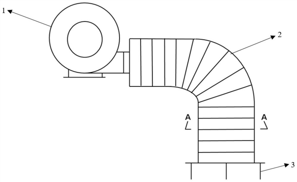
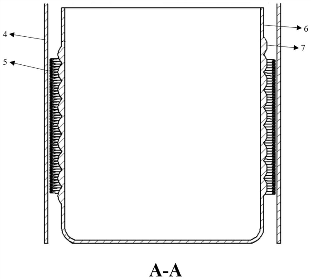
[0021] like figure 1 , figure 2 As shown, this embodiment includes: a blower 1 and a beaker 6 connected to it through an aluminum foil tube 2, wherein: the beaker 6 is provided with aluminum foil 4 outside, and the capillary reactor 5 and the ultraviolet LED lamp strip 7 are wound and arranged on the beaker 6 and between 4 sheets of aluminum foil.

[0022] The capillary reactor 5 is made of PFA, has an inner diameter of 1mm, a length of 12.5m, and a wall thickness of 0.3mm.

[0023] The blower 1 has an input power of 40W and an air volume of 1m 3 / min.

[0024] The aluminum foil tube 2 has an inner diameter of 120mm and a length of 1.5m, and can be stretched freely in the axial direction.

[0025] The material of the beaker 6 is silicate glass. Preferably, the inner diameter of the beaker is 80 mm, and the distance between the LED strip and the capillary is 5 mm.

[0026] The ultraviolet LED lamp strip 4 emits ultraviolet light with a characteristic wavelength of 365nm, ...

Embodiment 2

[0029] Compared with Example 1, the material of the capillary reactor 5 in this example is PFA, the inner diameter is 0.75mm, and the length is 8m.

[0030] The blower 1 has an input power of 60W and an air volume of 1.5m 3 / min

[0031] The inner diameter of the aluminum foil tube 2 is 120mm, and the length is 2m.

[0032] In this embodiment, the above system is used to carry out photosensitized cycloaddition reaction of norbornadiene. Preferably, the concentration of norbornadiene is 0.06mol / L, the photosensitizer used is tetraethyl Michler's ketone, and the solvent used is Acetone, the reaction residence time was 2 hours, and the product tetracycloheptane collected had a yield of 90%. Compared with the prior art where a single mercury lamp is used to irradiate the tank reactor, the reaction yield per hour is less than 20%.

Embodiment 3

[0034] Compared with Example 1, in this example, three groups of flexible light sources and capillary continuous flow reactors are set in parallel to increase the reaction flux per hour to 60mL / h.

[0035] In this embodiment, the above-mentioned system is used to carry out photosensitized cycloaddition reaction of norbornadiene. Preferably, the concentration of norbornadiene is 0.30mol / L, the photosensitizer used is tetraethyl Michler's ketone, and the solvent used is Acetone, the reaction residence time was 0.5 hour, and the product tetracycloheptane collected had a yield of 75%. Compared with the prior art where a single mercury lamp is used to irradiate the tank reactor, the space-time yield of the reaction is less than one-tenth of that of the continuous flow reactor.


PUM

PropertyMeasurementUnit
Wavelengthaaaaaaaaaa
Half widthaaaaaaaaaa
Optical poweraaaaaaaaaa

Abstract

The invention discloses an ultraviolet photochemical reaction system based on a continuous flow technology. The system comprises a capillary tube continuous flow reactor, a flexible light source and an air blower, the flexible light source is wound on the outer wall of a container, the capillary tube continuous flow reactor is wound on the outer side of the flexible light source and communicated with an air blower, and air is blown in by the air blower to conduct air cooling on the flexible light source and a capillary tube micro-reactor. The device can combine the advantages of photochemicalconversion and a continuous flow technology, and on the premise of safe production, the yield and purity of the product are improved as much as possible with low energy consumption.

Description

technical field [0001] The invention relates to a technology in the field of optical reaction, in particular to an ultraviolet photochemical reactor device based on continuous flow technology. Background technique [0002] Due to its green reaction process and mild reaction conditions, ultraviolet photochemical conversion has gradually attracted the attention of academia and industry. Existing ultraviolet photochemical reaction devices use low-pressure or medium-pressure mercury lamps as light sources. This kind of mercury lamp has defects such as high energy consumption, rapid temperature rise, and the need for external water-cooling equipment. In contrast, ultraviolet LED strips have small heat release, Strong light monochromaticity and other advantages. Contents of the invention [0003] Aiming at the above-mentioned background technology, the present invention proposes an ultraviolet photochemical reaction system based on continuous flow technology, which can combine ...

Claims


Application Information

Patent Timeline
IPC IPC(8): B01J19/12
CPCB01J19/123B01J19/0093B01J2219/00711B01J2219/0072B01J2219/00033
Inventor 苏远海沈冲商敏静王在良
Owner SHANGHAI JIAO TONG UNIV
Why Eureka
Try Eureka