Supercharge Your Innovation With Domain-Expert AI Agents!

Single-hand rapid-disengaging chuck

A technology of clipping and mandrel, applied in the directions of wrenches, screwdrivers, manufacturing tools, etc., can solve the problems of broken screwdriver heads, smashed people and objects, inconvenient use, etc., so as to reduce the number of times of falling and picking up, and reducing the number of times of use. , easy to use effect

Active Publication Date: 2017-03-15
美事满工具(海安)有限公司
View PDF6 Cites 3 Cited by
  • Summary
  • Abstract
  • Description
  • Claims
  • Application Information

AI Technical Summary

Problems solved by technology

[0002] Conventional casings are usually popped out, so that when the screwdriver head is inserted or pulled out relative to the mandrel, the casing must be retracted manually. The entire operation process is quite cumbersome, which increases the inconvenience of use, and the conventional screwdriver head is withdrawn. At this time, the bit of the screwdriver flies out of the mandrel quickly under the action of the elastic force accumulated in the mandrel. It is necessary to hold the bit with hands in advance, otherwise the bit of the screwdriver will fly out and fall to the ground. Especially when workers are working at heights, they need to climb It is very troublesome and time-consuming to pick up the dropped screwdriver bits only after getting off the ladder, and it is easy to cause the screwdriver bits to break. As a result, the chuck cannot be operated with one hand and needs to be operated with both hands. When people use electric tools, the other hand needs to operate electric tools, etc., which brings great operational troubles to the operators, inconvenient use, and affects normal operations.

Method used


Image

  • Single-hand rapid-disengaging chuck
  • Single-hand rapid-disengaging chuck
  • Single-hand rapid-disengaging chuck

Examples


Embodiment

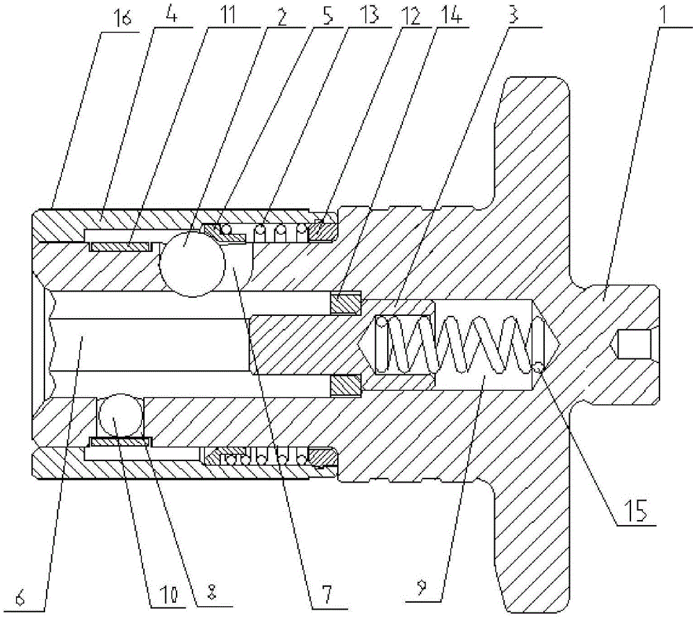
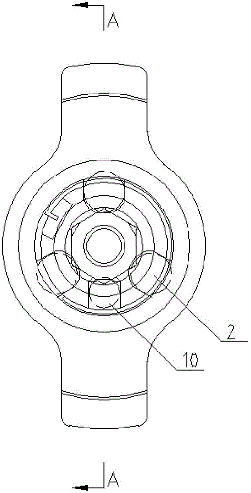
[0018] Embodiment: A one-handed quick-release chuck, including a mandrel 1, a sphere 2, a sliding pin 3, a jacket 4, a retaining ring 5 and an abutting member, and one end of the mandrel 1 forms an axial non-circular insert The slot 6, the mandrel 1 is located on the side wall of the slot 6 and is provided with at least one elongated radial perforation 7 extending in the axial direction and at least one radial groove 8, and the bottom surface of the slot 6 is recessed to form a circular Groove 9, the ball 2 can be slid and accommodated in the radial perforation 7 of the mandrel 1 along the extension direction of the radial perforation 7, the sphere 2 can be partially exposed into the slot 6, and the sphere 2 cannot completely fall into the slot 6 , the pressing piece is positioned in the radial groove 8 of the mandrel 1, one end of the pressing piece elastically protrudes into the slot 6, and the pressing piece will not completely fall into the slot 6, the sliding pin 3 axis I...


PUM


Abstract

The invention discloses a single-hand rapid-disengaging chuck. The side wall of a non-circular insertion groove at one end of a core shaft is provided with at least one long-strip-shaped radial through hole and at least one radial groove. The bottom face of the insertion groove is a circular groove. A ball can be contained in the radial through hole in the extending direction of the radial through hole in a sliding manner. A part of the ball can be exposed into the insertion groove and cannot fall into the insertion groove. One end of an abutting piece in the radial groove elastically extends into the insertion groove, and the abutting piece cannot fall into the insertion groove. One end of a sliding pin which can slide a set distance and is arranged in the circular groove in an insertion manner can elastically extend into the insertion groove. A sleeve can axially and elastically slide a set distance and then arranged on the outer side of the core shaft in a sleeving manner. A step hole with the internal diameter of one end being smaller than the internal diameter of the other end is formed in the inner side of the sleeve. The surface of the end, back onto the insertion groove, of the ball abuts against the side wall of the step hole. A baffle ring is arranged between the end, with the large diameter, of the sleeve and the core shaft. The baffle ring elastically abuts against the outer side surface, in the extending direction of the radial through hole of the core shaft, of the ball. The single-hand rapid-disengaging chuck is convenient to use.

Description

technical field [0001] The invention relates to the technical field of chucks, in particular to a one-handed quick release chuck. Background technique [0002] Conventional casings are usually popped out, so that when the screwdriver head is inserted or pulled out relative to the mandrel, the casing must be retracted manually. The entire operation process is quite cumbersome, which increases the inconvenience of use, and the conventional screwdriver head is withdrawn. At this time, the bit of the screwdriver flies out of the mandrel quickly under the action of the elastic force accumulated in the mandrel. It is necessary to hold the bit with hands in advance, otherwise the bit of the screwdriver will fly out and fall to the ground. Especially when workers are working at heights, they need to climb It is very troublesome and time-consuming to pick up the dropped screwdriver bits only after getting off the ladder, and it is easy to cause the screwdriver bits to break. As a re...

Claims


Application Information

Patent Timeline
IPC IPC(8): B25B23/00
CPCB25B23/00B25B23/0035
Inventor 黄国庆
Owner 美事满工具(海安)有限公司
Features
  • R&D
  • Intellectual Property
  • Life Sciences
  • Materials
  • Tech Scout
  • Unparalleled Data Quality
  • Higher Quality Content
  • 60% Fewer Hallucinations
Learn More