Draw gear component and railway vehicle provided with draw gear component

A rail vehicle and coupler technology, which is applied in the field of rail vehicles, can solve problems such as damage to upper equipment, limited energy absorption, and narrow space at the front end of the car, achieving the effect of improving passive safety

Active Publication Date: 2017-03-15
CRRC QINGDAO SIFANG CO LTD
View PDF5 Cites 9 Cited by
  • Summary
  • Abstract
  • Description
  • Claims
  • Application Information

AI Technical Summary

Problems solved by technology

[0003] At present, in order to reduce the air resistance and improve the starting performance of the train, the head of the train usually adopts a streamlined tip shuttle design; although this design reduces the running resistance of the train and increases the speed of the train, the space at the front end of the train is narrow and can only accommodate In the lower coupler part, it is no longer possible to arrange a large energy-absorbing mechanism
[0004] When two high-speed trains collide, the coupler is the first to be impacted. Although the coupler can be set as an energy-absorbing coupler, its energy absorption is limited and cannot completely absorb the energy generated by the collision of the train. During the process, the hidden danger of intruding into the upper part and damaging the upper part of the equipment, or falling onto the track increases the risk of derailment

Method used


Image

  • Draw gear component and railway vehicle provided with draw gear component
  • Draw gear component and railway vehicle provided with draw gear component
  • Draw gear component and railway vehicle provided with draw gear component

Examples


Embodiment Construction

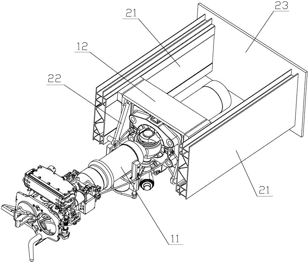
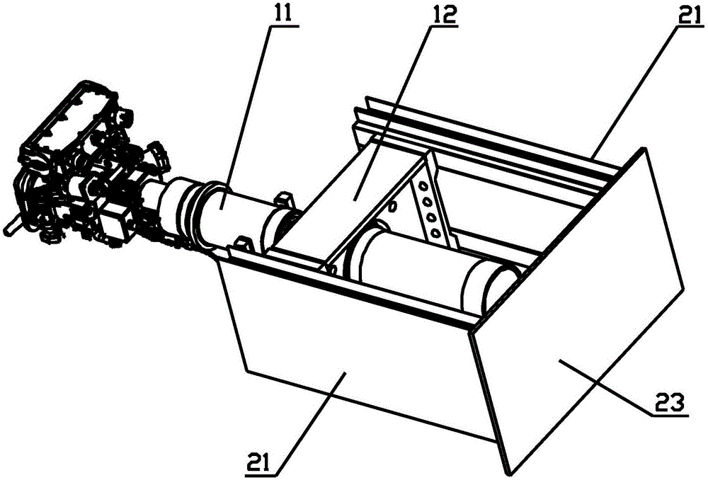
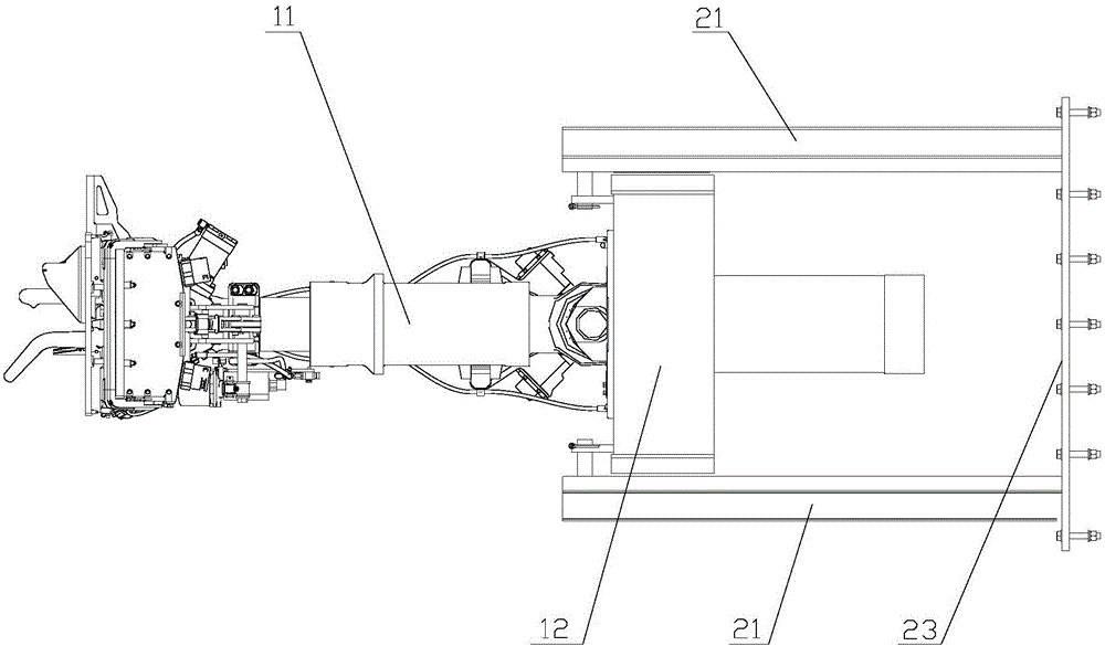
[0033] The core of the present invention is to provide a coupler assembly and a rail vehicle having the coupler assembly. The structural design of the coupler assembly can not only ensure the connecting function of the coupler during normal operation of the vehicle, but also avoid the retreat process of the coupler when the collision occurs. Intrusion into the upper part of the middle to damage the upper equipment or to fall on the track increases the risk of derailment, which can improve the passive safety of rail vehicle collisions.

[0034] In order to make those skilled in the art better understand the solution of the present invention, the present invention will be further described in detail below with reference to the accompanying drawings and specific embodiments.

[0035] Please refer to Figure 1 to Figure 4 ,in, figure 1 A schematic structural diagram of a specific embodiment of the coupler assembly provided by the present invention; figure 2 for figure 1 Schema...


PUM


Abstract

The invention discloses a draw gear component and a railway vehicle provided with the draw gear component. The draw gear component comprises: a draw gear mounting seat, and a draw gear, fixedly installed on the draw gear mounting seat. The draw gear component further comprises: a support component and a revolving part which are arranged on two sides of the draw gear mounting seat, wherein one end of the revolving part is in rotational connection with the lower end of the support component, and the rotational center thereof is arranged horizontally and is vertical to the length direction of the railway vehicle; the other end of the revolving part is hinged with the upper end of the draw gear mounting seat; and the configuration is that: in an initial state, the draw gear mounting seat is fixedly connected with the support component, and the hinge point of the revolving part and the draw gear mounting seat is positioned above the rotational connection point of the revolving part and the support component. The structural design of the draw gear component can guarantee the coupling function of the draw gear during normal operation, and when a collision happens, the draw gear not only cannot intrude into an upper part to destroy upper equipment but also cannot drop down to a railway to increase the derail danger in the retreating and energy absorbing process, so that the passive safety of a railway vehicle collision can be improved.

Description

technical field [0001] The present invention relates to the technical field of rail vehicles, in particular to a coupler assembly and a rail vehicle having the coupler assembly. Background technique [0002] With the improvement of the speed of high-speed rail, passive safety has attracted more and more attention. [0003] At present, in order to reduce the air resistance and improve the starting performance of the train, the head of the train usually adopts a streamlined pointed shuttle design. Although this design reduces the running resistance of the train and increases the speed, the space at the front end of the train is narrow and can only accommodate In the part of the lower coupler, the large energy-absorbing mechanism can no longer be arranged. [0004] When two high-speed trains collide, the coupler part is the first to be impacted. Although the coupler can be set as an energy-absorbing coupler, its energy absorption is limited and cannot fully absorb the energy g...

Claims


Application Information

Patent Timeline
Patent Type & Authority Applications(China)
IPC IPC(8): B61G7/12B61G7/14
CPCB61G7/12B61G7/14
Inventor 赵士忠张永贵陶桂东龚明田爱琴于洋洋王晋乐
Owner CRRC QINGDAO SIFANG CO LTD
Why Eureka
Try Eureka