
Three-way oil fume separation device of integrated cooker

A technology of oil fume separation and integrated stoves, which is applied in the field of integrated stoves, and can solve problems such as easy fires, environmental sanitation, and odors

Active Publication Date: 2017-03-15
林志斌
View PDF8 Cites 4 Cited by
  • Summary
  • Abstract
  • Description
  • Claims
  • Application Information

AI Technical Summary

Problems solved by technology

The existing integrated stove sucks the oil fume, passes through the air suction duct, the smoke collecting box and the motor wind wheel, and finally discharges it from the oil fume pipe. Since the oil and smoke are mixed and discharged together, after long-term use, oil stains will accumulate in the oil fume pipe and A large amount of oil accumulated on the motor, wind wheel and other components will produce peculiar smell, affect environmental sanitation, and easily cause fire
Therefore, the applicant has applied for a Chinese utility model patent 201620106204.8, the patent name is "integrated cooker vortex type lampblack separation and diversion device", which mainly arranges 10-20 vortex cyclone tubes in parallel in the suction duct or the upper mouth of the smoke collection box , the lower part of the vortex cyclone tube is located under each spiral groove and connected to the drainage rod, and the oil fume is separated through the vortex cyclone tube, and the separated oil is collected into the oil receiving box through the drainage rod and the inner walls of both sides of the smoke collection box. This structure only Install a vortex cyclone tube for oil fume separation in the suction duct or smoke collection box, which has a limited effect of oil fume separation. If the oil fume is too large, some oil stains and smoke will still be discharged to the oil fume pipe and the motor wind wheel, etc. parts

Method used


Image

  • Three-way oil fume separation device of integrated cooker
  • Three-way oil fume separation device of integrated cooker
  • Three-way oil fume separation device of integrated cooker

Examples


Embodiment Construction

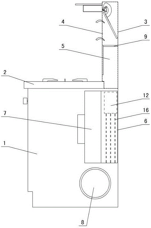
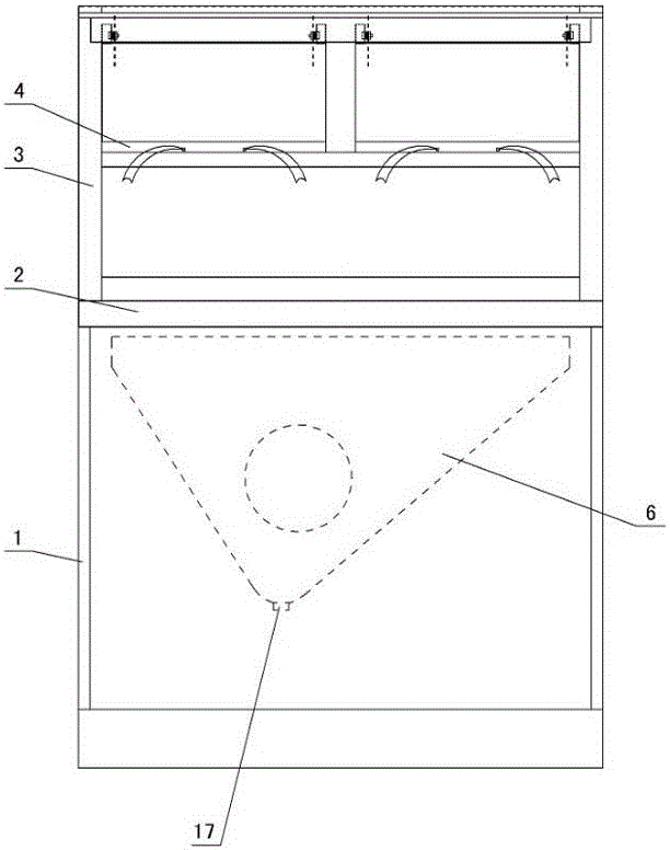
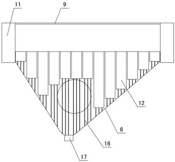
[0013] The invention relates to a three-channel oil fume separation device for an integrated stove, such as figure 1 — Image 6 As shown, it includes a box body 1, a stove 2 is arranged on the box body, a side suction plate 3 is arranged on the stove top, a side suction hole 4 is formed on the wall of the side suction plate, and a suction channel 5 is opened in the side suction plate , the smoke collection box 6 and the wind wheel 7 are arranged in the box, the side outlet of the smoke collection box is connected to the wind wheel, and the wind wheel is connected to the air outlet 8, and it is characterized in that: the suction channel 5 located at the side suction hole 4 Install a mesh plate 9 with a separation mesh 10 in the mesh plate, oil collecting boxes 11 are arranged on both sides of the mesh plate, 10-20 vortex cyclone tubes 12 are arranged side by side in the smoke collecting box 6, and the middle part of the vortex cyclone tube is a through hole 13. The inner wall ...


PUM


Abstract

The invention relates to a three-way oil fume separation device of an integrated cooker. The three-way oil fume separation device comprises a case body, wherein a cooking bench is arranged on the case body, a side suction plate is arranged on the cooking bench, a side suction hole is formed in the wall of the side suction plate, a suction channel is formed in the side suction plate, a fume collecting box and a wind wheel are arranged in the case body, a side outlet of the fume collecting box is connected with the wind wheel, and the wind wheel is connected with an air outlet. The three-way oil fume separation device is characterized in that a net plate is arranged in the suction channel located at the side suction hole, a separating mesh is arranged in the net plate, oil collecting boxes are arranged on both sides of the net plate, 10 to 20 vortex cyclone tubes are arranged in the fume collecting box in parallel, through holes are formed in the middle of the vortex cyclone tubes, 3 to 10 spiral grooves are formed in the inner walls of the vortex cyclone tubes, spiral convex ribs are arranged between the spiral grooves, diversion rods are connected to the lower parts of the vortex cyclone tubes, the lower ends of the diversion rods make contact with the inner walls of the left and right sides of the fume collecting box, an oil outlet is formed in the bottom of the fume collecting box, the oil outlet is connected with a waste oil collecting box through a tube, crossed steel wire meshes are arranged at a side outlet of the fume collecting box, and a separation blocking piece is arranged at the intersection of the steel wire meshes.

Description

technical field [0001] The invention relates to an integrated cooker, in particular to a three-channel oil fume separation device for the integrated cooker. Background technique [0002] The integrated stove is a kitchen appliance that integrates multiple functions such as a range hood, a gas stove, and a storage cabinet. It has the advantages of space saving, convenient use, energy saving, low consumption, and environmental protection. It is widely used in current home kitchens. The existing integrated stove sucks the oil fume, passes through the air suction duct, the smoke collecting box and the motor wind wheel, and finally discharges it from the oil fume pipe. Since the oil and smoke are mixed and discharged together, after long-term use, oil stains will accumulate in the oil fume pipe and A large amount of oil accumulated on components such as motors, wind wheels, etc. will produce odors, affect environmental sanitation, and easily cause fires. Therefore, the applicant...

Claims


Application Information

Patent Timeline
Patent Type & Authority Applications(China)
IPC IPC(8): F24C15/20
CPCF24C15/2042
Inventor 林志斌
Owner 林志斌
Learn More