Check patentability & draft patents in minutes with Patsnap Eureka AI!

Light guide plate and light source module

A light source module and light guide plate technology, applied in the direction of light guides, optics, optical components, etc., can solve problems such as optimization of the light utilization rate of light source modules, achieve good light utilization rate and luminance, and reduce energy loss.

Active Publication Date: 2020-04-17
YANGXIN TECH SUZHOU
View PDF5 Cites 0 Cited by
  • Summary
  • Abstract
  • Description
  • Claims
  • Application Information

AI Technical Summary

Problems solved by technology

[0003] In the known technology, the improvement of microstructure (such as position or shape, etc.) mainly focuses on the improvement of the light uniformity of the light source module, and seldom optimizes the light utilization rate of the light source module

Method used


Image

  • Light guide plate and light source module
  • Light guide plate and light source module
  • Light guide plate and light source module

Examples


Embodiment Construction

[0030] The foregoing and other technical contents, features and effects of the present invention will be clearly presented in the following detailed description of a preferred embodiment with reference to the accompanying drawings. The directional terms mentioned in the following embodiments, such as: up, down, left, right, front or back, etc., are only referring to the directions of the drawings. Accordingly, the directional terms are used to illustrate and not to limit the invention.

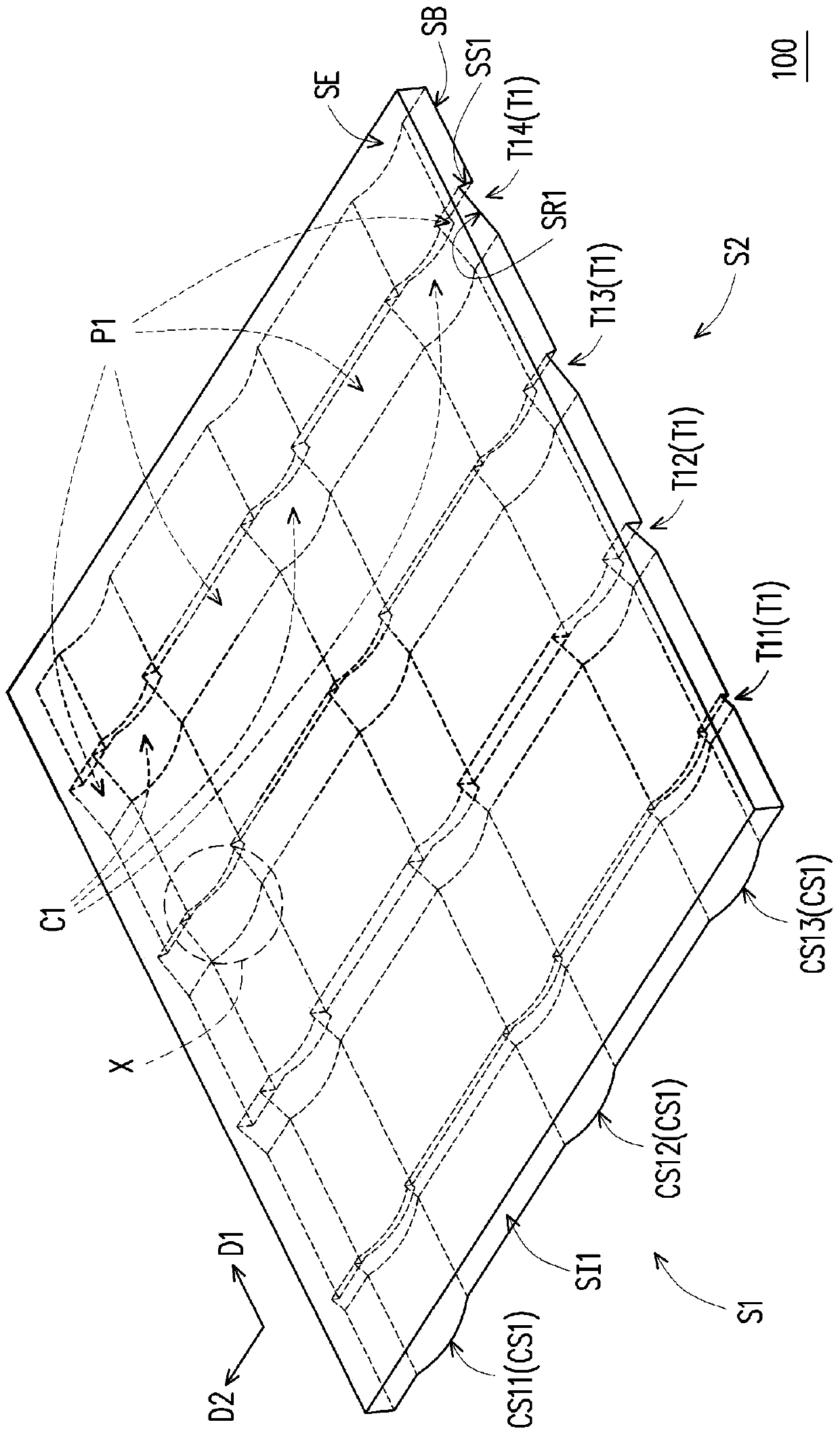
[0031] Figure 1A is a schematic diagram of a light guide plate according to the first embodiment of the present invention. Figure 1B and Figure 1C are Figure 1A A schematic side view of the first side S1 and the second side S2 of the middle light guide plate. Please refer to Figure 1A to Figure 1C , the light guide plate 100 includes a first light incident surface SI1 , a light exit surface SE and a bottom surface SB. The bottom surface SB is opposite to the light emitting surface SE, a...


PUM


Abstract

The present invention discloses a light guide plate and a light source module, wherein the light guide plate includes a light entrance surface, a light exit surface and a bottom surface. The bottom surface is formed with a plurality of strip-like grooves. The arrangement of the strip-like grooves is perpendicular to the incoming light. The depth of the bar-shaped groove and the width of the bar-shaped groove in the arrangement direction increase as the distance between the strip-like groove and the incoming light is increased. Each of the strip-like grooves has a first smoothing surface and a backlit surface. The first glide is located between the first and the back. Each of the first light-receiving surfaces includes a plurality of first planes, and the first planes are arranged along the extending direction of each of the first-shaped grooves.

Description

technical field [0001] The invention relates to an optical element and an optical module, and in particular to a light guide plate and a light source module. Background technique [0002] The light source module is mainly divided into a direct type light source module and a side light type light source module according to the position of the light source. Taking the side-illuminated light source module as an example, it usually includes a light guide plate and a light source disposed on the side of the light guide plate. After the light beam emitted by the light source enters the light guide plate, the light beam will be confined in the light guide plate due to total reflection. By forming multiple microstructures on the bottom surface of the light guide plate to destroy the total reflection, the light beam can be smoothly emitted from the light emitting surface of the light guide plate. [0003] In the known technologies, the improvement of the microstructure (such as pos...

Claims


Application Information

Patent Timeline
Patent Type & Authority Patents(China)
IPC IPC(8): G02B6/00
CPCG02B6/0038G02B6/0058
Inventor 邱文彦李清祥李建辉周民俊
Owner YANGXIN TECH SUZHOU
Features
  • R&D
  • Intellectual Property
  • Life Sciences
  • Materials
  • Tech Scout
  • Unparalleled Data Quality
  • Higher Quality Content
  • 60% Fewer Hallucinations
Learn More