Check patentability & draft patents in minutes with Patsnap Eureka AI!

Antenna device and radio communication apparatus

Inactive Publication Date: 2006-05-25
NEC CORP
View PDF5 Cites 13 Cited by
  • Summary
  • Abstract
  • Description
  • Claims
  • Application Information

AI Technical Summary

Benefits of technology

[0010] In the invention, it is possible to control the directivity with the use of a single antenna. Further, the use of a single antenna allows the antenna device to be so small that the antenna device can be built in cellular phones or the like. Furthermore, it is possible to optimally set the directivity according to communication states.

Problems solved by technology

It is difficult to change the direction of the directivity with the use of only a single patch antenna.
It is also difficult for this antenna to change the directivity.

Method used


Image

  • Antenna device and radio communication apparatus
  • Antenna device and radio communication apparatus
  • Antenna device and radio communication apparatus

Examples


Embodiment Construction

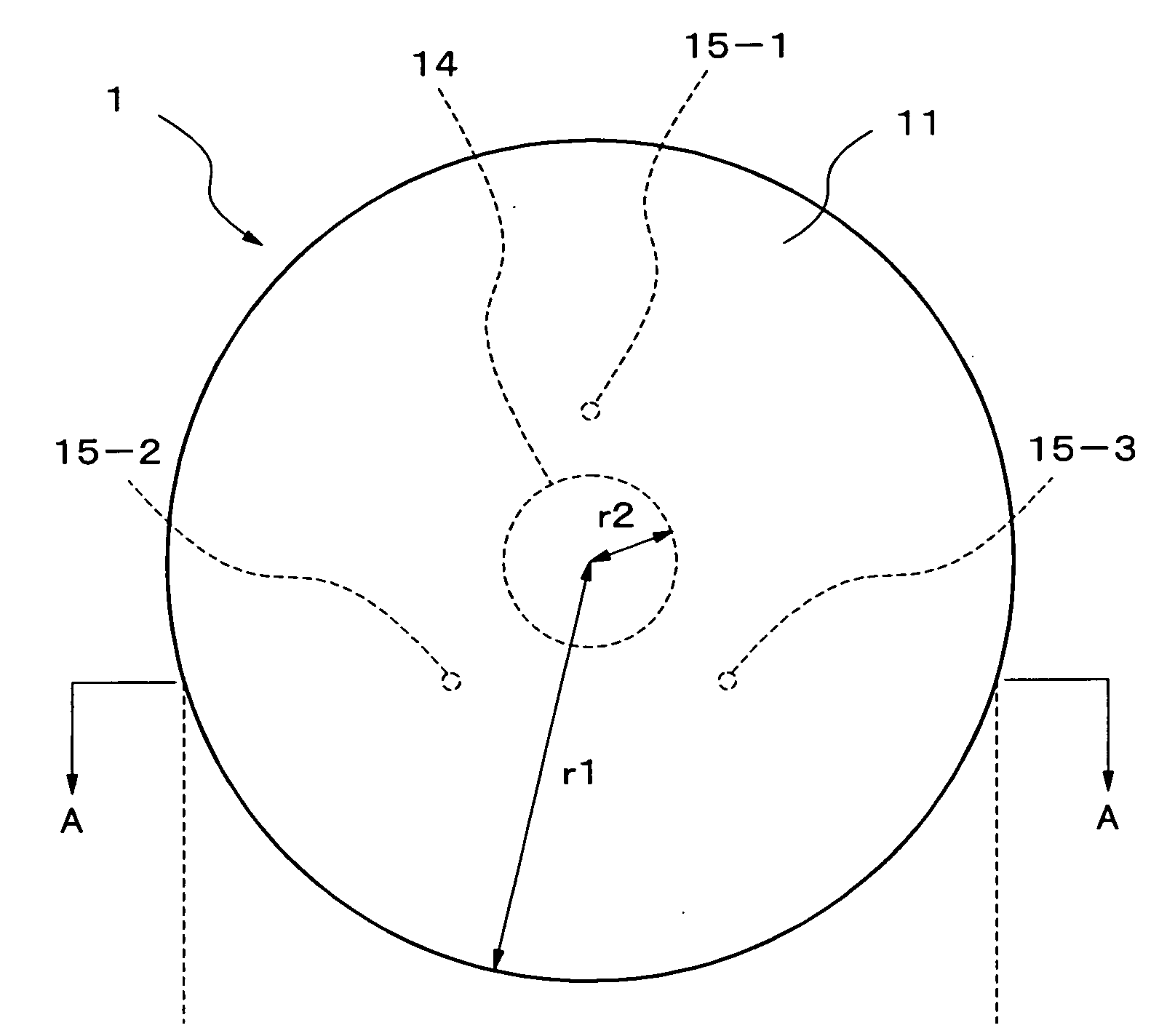
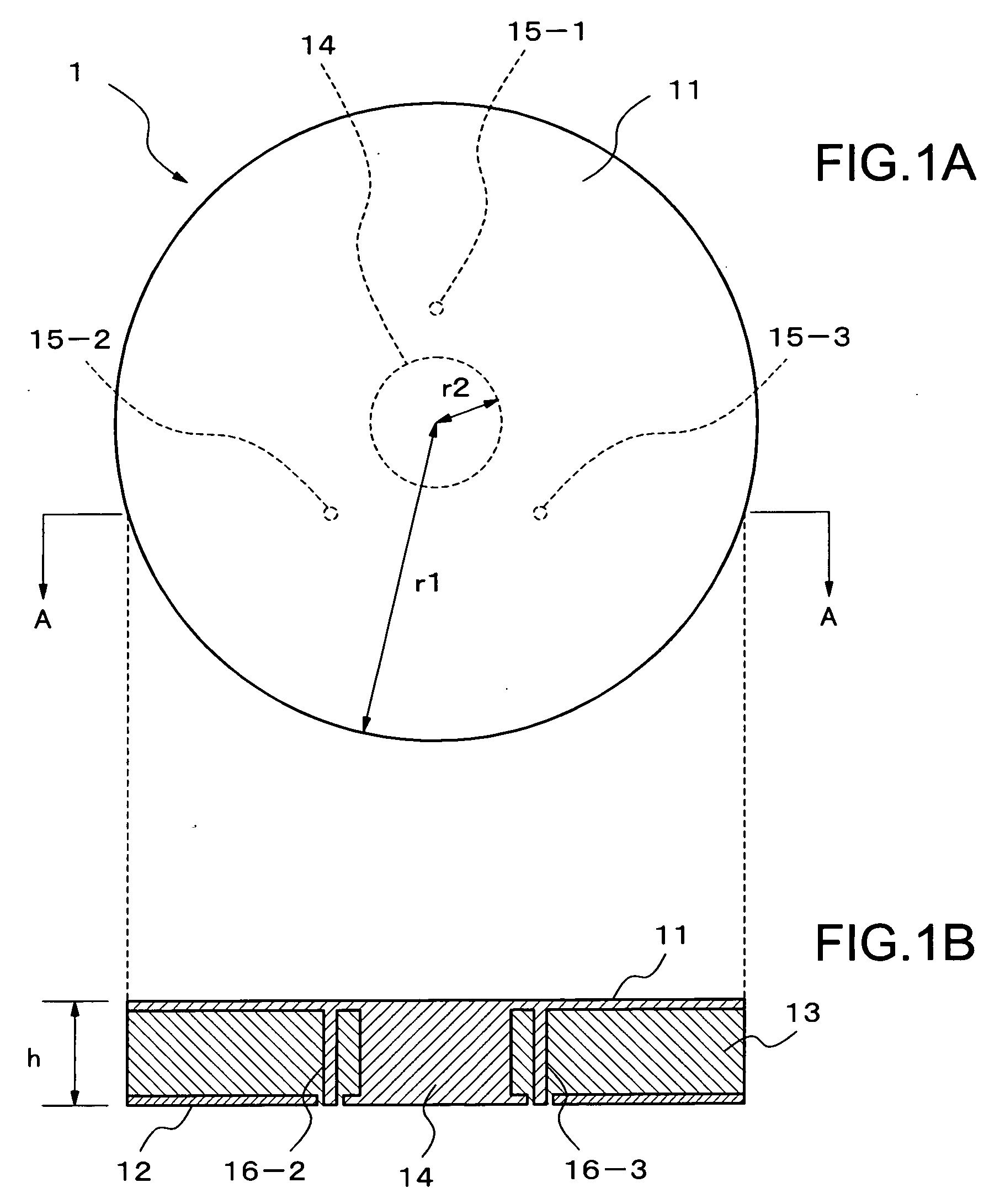
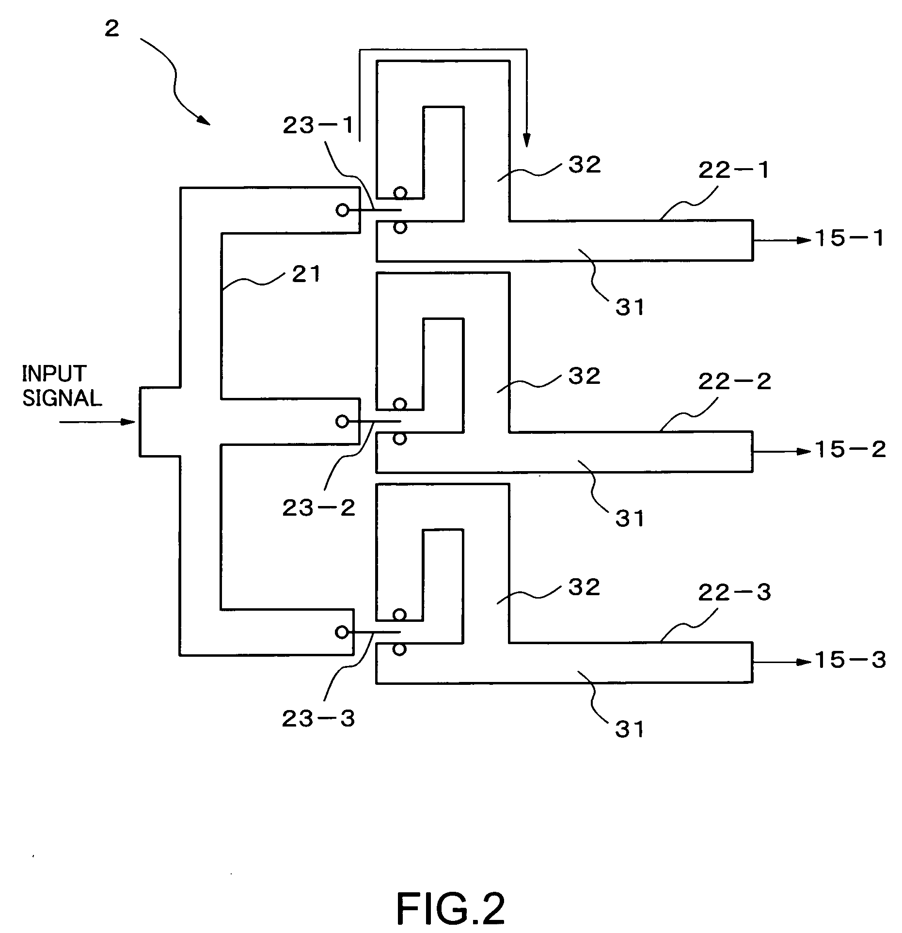
[0017] Hereinafter, a preferred exemplary embodiment of the present invention will be described. An antenna device according to the example of the present invention includes an antenna main body 1 having plural layers, and a feeder circuit 2 for feeding an electrical signal to the antenna main body 1. Referring to FIGS. 1A and 1B, the antenna main body 1 has an antenna element 11 serving as an upper layer, a ground layer 12 serving as a lower layer, and a dielectric layer 13 disposed between the upper layer and the lower layer. Disposed on the antenna element 11 are three electricity feeding points 15-1, 15-2, and 15-3. The antenna main body 1 is a patch antenna having a planar inverted-F antennas structure. The antenna main body 1 further includes: a cylindrical conductor 14, namely, a center post, for connecting a center part of the antenna element 11 to a center part of the ground layer 12; and three feeder conductors 16-1, 16-2, and 16-3 which are respectively provided for the e...


PUM


Abstract

An antenna device includes an antenna main body having at least three electricity feeding points and a feeder circuit for feeding an electrical signal to the antenna main body. The feeder circuit feeds electrical signals different in at least one of amplitude and phase to the electricity feeding points. The device enables to control the directivity with the use of a single antenna.

Description

BACKGROUND OF THE INVENTION [0001] 1. Field of the Invention [0002] The present invention relates to an antenna device, and more particularly to an antenna device capable of controlling its directivity, and a radio communication apparatus using the antenna device. [0003] 2. Description of the Related Art [0004] Most mobile communication terminals use a nondirectional antenna as an antenna device, because the direction toward a base station to be communicated with always changes. Meanwhile, in recent years, cellular phones, as an example of mobile communication terminals, have come to have a large number of functions. Those functions include website browsing, video telephone, photographing still images or moving images, navigation using the global positioning system, and authentication and checkout using a radio frequency identification technique. In order to implement such various functions, excellent antenna characteristics must be maintained irrespective of the use states of the c...

Claims


Application Information

Patent Timeline
IPC IPC(8): H01Q1/38
CPCH01Q1/243H01Q3/26H01Q9/0421H01Q21/20
Inventor FUKUDA, JUNICHI
Owner NEC CORP
Features
  • R&D
  • Intellectual Property
  • Life Sciences
  • Materials
  • Tech Scout
  • Unparalleled Data Quality
  • Higher Quality Content
  • 60% Fewer Hallucinations
Learn More