An electric powder spraying device

A power supply device and powder spraying technology, which is applied in the device, application, animal husbandry and other directions of catching or killing insects to achieve the effect of uniform distribution and continuous concentration

Active Publication Date: 2022-07-22
刘柱源
View PDF6 Cites 0 Cited by
  • Summary
  • Abstract
  • Description
  • Claims
  • Application Information

AI Technical Summary

Problems solved by technology

[0002] The same applicant of this application has previously submitted a patent application titled "An Electric Particle Spraying Device", the publication number is "CN 106035302 A", which uses a suction nozzle that can move up and down, by adjusting the up and down position of the suction nozzle In order to adjust the concentration of the air-powder mixture, this electric particle spraying device uses electric tools instead of the previous manual operation mode, which has indeed effectively improved the spraying efficiency and quality of the powder, and reduced labor intensity, but in the subsequent actual use process , the applicant found that with the gradual reduction of the amount of powder in the powder bin, the distance between the powder surface and the suction nozzle is also increasing, and the concentration of the sprayed air-powder mixture is also gradually decreasing. Only by adjusting the position of the suction nozzle can the concentration of the sprayed gas-powder mixture be stable, that is to say, the above-mentioned technical scheme has shortcomings in terms of the stability of the concentration of the gas-powder mixture

Method used


Image

  • An electric powder spraying device
  • An electric powder spraying device
  • An electric powder spraying device

Examples


Embodiment Construction

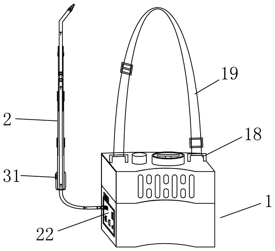
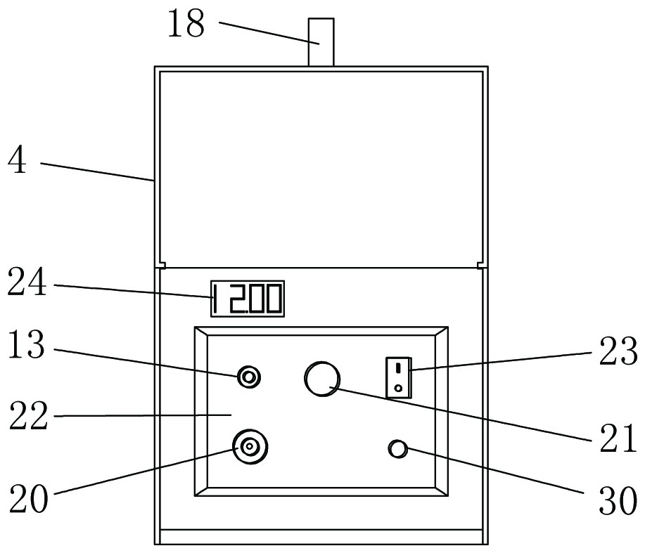
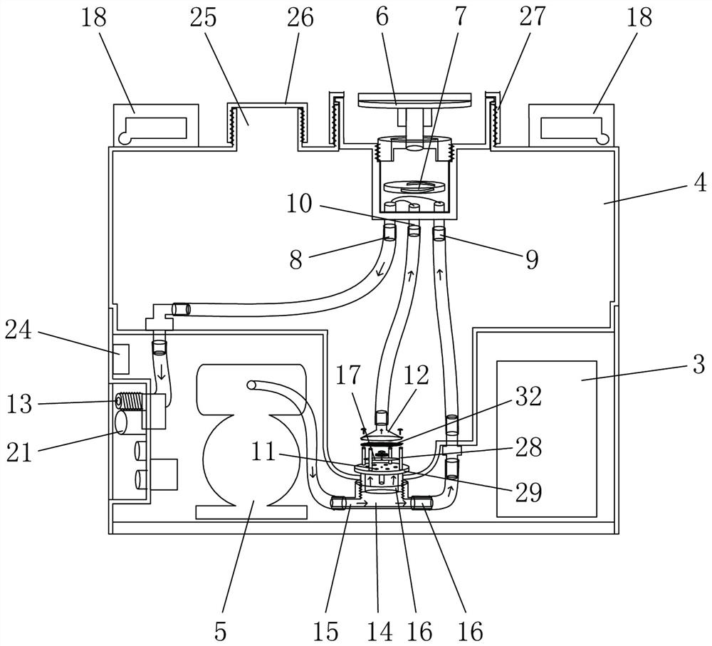
[0019] refer to Figure 1 to Figure 4 , an electric powder spraying device, including a main engine 1 and a discharging rod 2, the main engine 1 includes a controller, a power supply device 3, a powder bin 4 and an air supply device 5, and the main engine 1 is also provided with an adjustment handle 6. Proportional valve 7; the proportional valve 7 is provided with a powder outlet 8, a proportional valve air inlet 9 and a powder inlet 10; the lower part of the powder bin 4 is provided with a through hole; the upper part of the through hole is provided with a powder suction The cover 12, the proportional valve air inlet 9 and the through hole are connected with the air supply device 5 through a hose, the powder suction cover 12 is connected with the powder inlet 10 through a hose, and the powder outlet 8 It is connected with the discharge pipe joint 13 arranged on the side wall of the main machine 1 through a hose, and the discharge rod 2 is connected with the discharge pipe jo...


PUM


Abstract

The invention discloses an electric powder spraying device, comprising a main engine and a discharging rod. The main engine includes a controller, a power supply device, a powder bin and an air supply device. The main engine is also provided with a proportional valve with an adjustment handle; the proportional valve is provided with powder material The outlet, the air inlet of the proportional valve and the powder inlet; the lower part of the powder bin is provided with a through hole; the upper part of the through hole is provided with a powder suction cover; the proportional valve air inlet and the through hole are connected with the air supply device, and the powder suction cover is connected with the powder The material inlet is connected, and the proportional valve is used to adjust the concentration of the sprayed powder, so that the continuous high-concentration gas-powder mixture and air are mixed at the powder outlet of the proportional valve, and the concentration of the sprayed gas-powder mixture will not change with the amount of powder in the powder silo. It can be changed by increasing or decreasing, so that the concentration of the sprayed air-powder mixture can be continuous and stable, the air-powder mixture is evenly distributed in the termite passage, and can enter the ant nest through the termite passage and sprinkle on most of the termites, which is easy to control. The purpose of the entire nest of termites.

Description

technical field [0001] The invention relates to a tool for killing termites and other pests, in particular to a particle spraying device. Background technique [0002] The same applicant of the present application has previously submitted a patent application entitled "An Electric Particle Spraying Device", the publication number is "CN 106035302 A", which adopts a suction nozzle that can move up and down, and adjusts the upper and lower positions of the suction nozzle In order to adjust the concentration of the gas-powder mixture, this electric particle spraying device uses electric tools instead of the previous manual operation mode, which effectively improves the spraying efficiency and spraying quality of the powder, and reduces the labor intensity, but in the subsequent actual use process. , the applicant found that as the amount of powder in the powder silo gradually decreased, the distance between the powder surface and the suction nozzle was also increasing, and the ...

Claims


Application Information

Patent Timeline
Patent Type & Authority Patents(China)
IPC IPC(8): A01M9/00
CPCA01M9/0046
Inventor 刘柱源
Owner 刘柱源
Why Eureka
Try Eureka