
Method and apparatus for supplying hydrogen selenide mixed gas for solar cell

A technology of solar cells and mixed gases, applied in binary selenium/tellurium compounds, photovoltaic power generation, climate sustainability, etc., can solve the problem that flow control is no longer effective, gas supply cannot be guaranteed, and the frequency of replacement of gas storage cylinders is increasing, etc. question

Inactive Publication Date: 2014-09-24
NIPPON SANSO CORP
View PDF7 Cites 0 Cited by
  • Summary
  • Abstract
  • Description
  • Claims
  • Application Information

AI Technical Summary

Problems solved by technology

Therefore, there is a problem that if a gas cylinder filled with a mixed gas adjusted to a predetermined concentration is used, the frequency of replacement of the gas cylinder will increase, and a sufficient gas supply cannot be ensured.
This phenomenon leads to the problem that the flow control becomes no longer effective
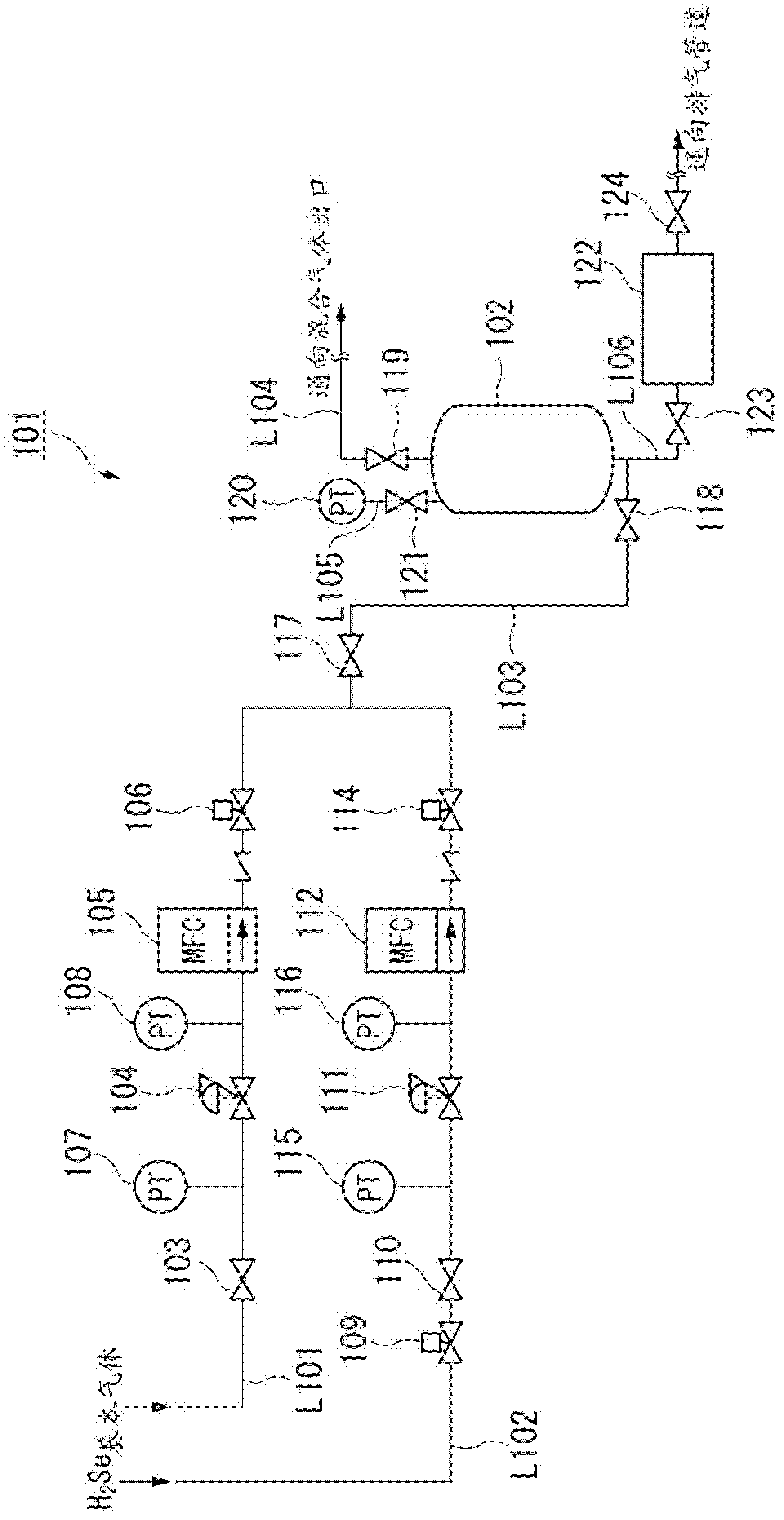
In this way, if the flow control becomes ineffective, the mass flow controller (MFC) 112 for 100% hydrogen selenide gas judges that a smaller amount of gas flows than actually flows and opens the control valve, resulting in a higher than designed flow rate. Set a higher volume of gas to flow through
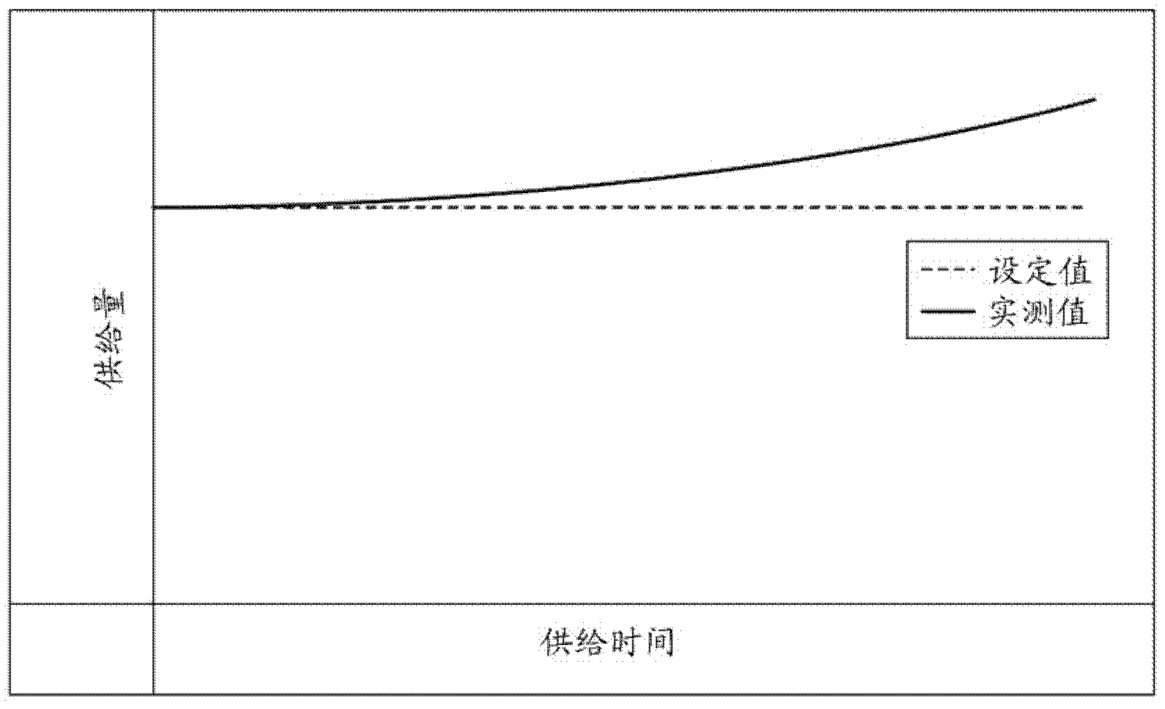
As a result, the following problems occur: from the start of supplying the hydrogen-selenide mixed gas, as time elapses, the concentration (set value) of the hydrogen-selenide mixed gas as the target and the concentration of the actually prepared hydrogen-selenide mixed gas ( The error between measured values) will increase (called drift phenomenon (reference image 3 ))

Method used


Image

  • Method and apparatus for supplying hydrogen selenide mixed gas for solar cell
  • Method and apparatus for supplying hydrogen selenide mixed gas for solar cell
  • Method and apparatus for supplying hydrogen selenide mixed gas for solar cell

Examples


example 1

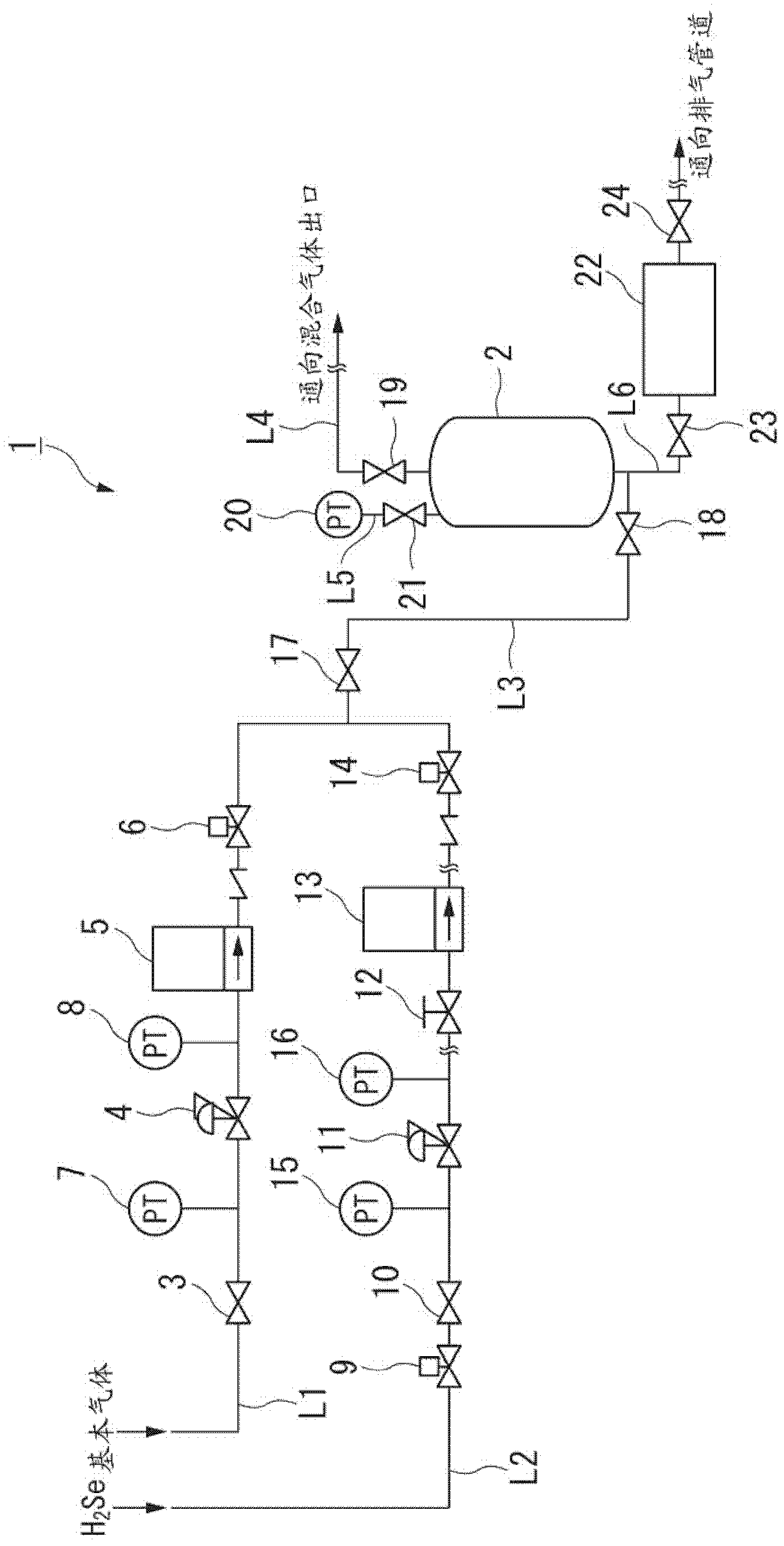
[0087] use figure 1 The shown supply device 1 continuously supplies hydrogen-selenide mixed gas to a solar cell manufacturing device. When continuously supplying the hydrogen-selenide mixed gas to the solar cell manufacturing apparatus, a batch process method using the buffer tank 2 was adopted.

[0088] In addition, the conditions of Table 1 were used as conditions at the time of supplying hydrogen-selenide mixed gas by the supply apparatus 1.

[0089] After performing 50 batch processes according to the conditions in Table 1, use the gas concentration analyzer 22 connected to the buffer container 2 to record the concentration change of the mixed gas. Table 2 shows the results.

example 2

[0091] use figure 2 The shown supply device 101 continuously supplies hydrogen-selenide mixed gas to a solar cell manufacturing device. When continuously supplying the hydrogen-selenide mixed gas to the solar cell manufacturing apparatus, a batch method using the buffer tank 102 was adopted, and the conditions in Table 1 were used as the conditions for supplying the hydrogen-selenide mixed gas from the supply device 101 .

[0092] After performing 50 batch processes according to the conditions in Table 1, use the gas concentration analyzer 122 connected to the buffer container 102 to record the concentration change of the mixed gas. Table 2 shows the results.

[0093]

[0094] Table 1

[0095]

example 1

Example 2

Set concentration [%]

10.00

10.00

Measured concentration after 50 batches [%]

10.10

11.31

Concentration change [%]

+0.10

+1.31

[0096] Table 2

[0097] As shown in Table 2, in the buffer c...


PUM


Abstract

The method for supplying a hydrogen-selenide mixed gas for solar cells of the present invention has a supply process, wherein the inert gas supplied from the basic gas supply flow path (L1) and the 100% selenide gas supplied from the raw material gas supply flow path (L2) The hydrogen gas is mixed to supply the hydrogen-selenide mixed gas adjusted to a predetermined concentration. In the supply process, the 100 The flow control of % hydrogen selenide gas is specified flow, and by the pressure control unit (13) that the downstream side of described flow control unit (12) is provided with, described flow control unit (12) and this pressure control unit ( 13) The pressure of the 100% hydrogen selenide gas between them is controlled to a specified pressure.

Description

technical field [0001] The present invention relates to a method for supplying a hydrogen-selenide mixed gas for a solar cell and an improvement of a supply device. [0002] This application claims priority based on Japanese Patent Application No. 2009-205230 for which it applied in Japan on September 4, 2009, and uses the content here. Background technique [0003] In recent years, due to problems such as environmental pollution, global warming, and depletion of fossil fuels, solar cells have attracted attention as an energy alternative to petroleum. Copper indium gallium selenide (CIGS, Cu(InGa)Se) series thin-film solar cells, which are the current mainstream solar cells, for example, the compound solar cell of Patent Document 1 is known. [0004] Patent Document 1 discloses a chalcopyrite-type light-absorbing layer containing copper, indium, gallium, and selenium, and a method for producing the same. Specifically, the chalcopyrite-type light-absorbing layer thin film i...

Claims


Application Information

Patent Timeline
Patent Type & Authority Patents(China)
IPC IPC(8): C01B19/04
CPCC01B19/04Y02E60/327Y02E60/324Y02E10/541Y02P70/50Y02E60/32
Inventor 伊藤吉则高桥康弘
Owner NIPPON SANSO CORP
Learn More