
System and method for erecting side-span girder section of cable-stayed bridge

A cable-stayed bridge and side span technology, applied in bridge construction, bridges, erection/assembly of bridges, etc., can solve the problems of increasing the foundation requirements of the support, affecting the stability, increasing the support material, etc., achieving adjustable traction slip, Improve the stability and strengthen the effect of the reinforcement cage

Active Publication Date: 2019-05-14
ROAD & BRIDGE SOUTH CHINA EINGINEERING CO LTD +1
View PDF8 Cites 0 Cited by
  • Summary
  • Abstract
  • Description
  • Claims
  • Application Information

AI Technical Summary

Problems solved by technology

However, when the construction environment of the bridge is harsh, with exposed rock strata, windy and high wind speed, and part of the riverbed will be exposed during the dry season, it will make it impossible for the beam section to be directly transported to the installation location during the dry season; There is no covering layer at the location, and the construction here increases the requirements for the support foundation. At the same time, the erection of high supports will also affect its stability due to the wind; and when the requirements for the support structure increase, it will inevitably lead to The increase of materials leads to the increase of construction cost
Therefore, for this choice, the side-span push-in-place welding is adopted first, and the mid-span is closed and then lowered for construction, which is extremely difficult to construct.

Method used


Image

  • System and method for erecting side-span girder section of cable-stayed bridge
  • System and method for erecting side-span girder section of cable-stayed bridge
  • System and method for erecting side-span girder section of cable-stayed bridge

Examples


Embodiment Construction

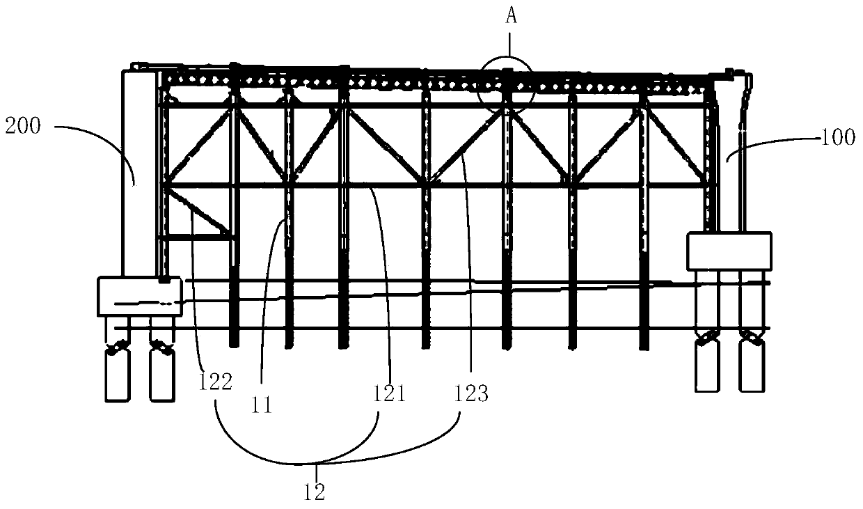
[0045] Embodiments of the present invention are described in detail below, examples of which are shown in the drawings, wherein the same or similar reference numerals designate the same or similar elements or elements having the same or similar functions throughout. The embodiments described below by referring to the figures are exemplary only for explaining the present invention and should not be construed as limiting the present invention.

[0046] For the construction of cable-stayed bridges, according to different construction techniques, it can be divided into beam section construction in cable tower area, standard beam section construction, temporary pier top beam section construction, beam section construction in shoal area, side span beam section construction, mid-span beam section construction, etc. Helong beam section construction; in the present embodiment, a cable-stayed bridge side span beam section erection system is provided, which includes:

[0047] Side-span s...


PUM


Abstract

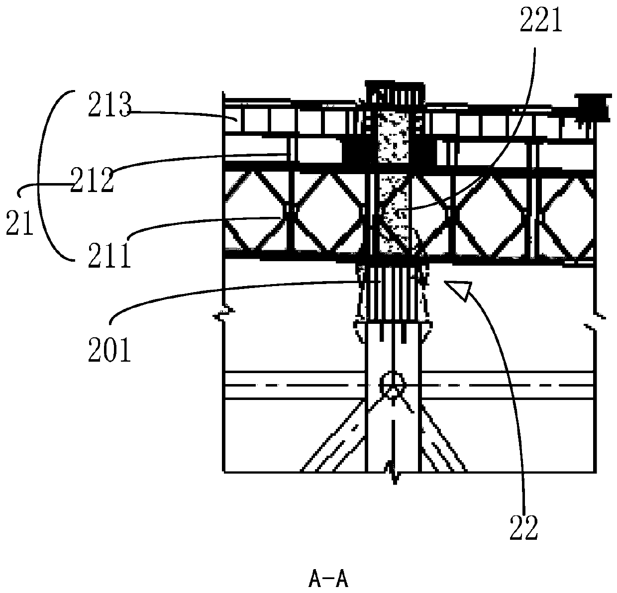
The invention provides a cable-stayed bridge side span beam section erecting system which comprises a side span support, a gliding traction system and a pushing closure system, wherein the side span support is erected between side span area bridge piers, and comprises a lower stressed structure and an upper stressed structure, the lower stressed structure comprises a plurality of steel tube stand columns arranged in the bridge longitudinal direction and support structures between the stand columns, and the upper stressed structure comprises a beam section gliding foundation and a beam section frame removing foundation; and the gliding traction system is arranged on the upper stressed structure, and comprises a gliding device used for gliding of a bearing beam section and a traction device used for providing traction force for gliding of the beam section; and the pushing closure system comprises a gliding support pier device distributed on the side span area bridge piers and the side span area support, and a pushing closure device. The cable-stayed bridge side span beam section erecting system adapts to erecting systems. The invention further provides an erecting method. Through the scheme, the installing precision of a side span beam section and the stability of the support structure can be improved.

Description

technical field [0001] The invention relates to the technical field of civil engineering, in particular, the invention relates to a system and a method for erecting side-span girder sections of a cable-stayed bridge. Background technique [0002] At present, the main girder installation methods for the side spans of cable-stayed bridges are the assembly method of parts and the whole segment assembly method; the part assembly method is to hang the steel beam first, and then hoist the bridge deck; the whole segment assembly method is to pass the bridge Surface mobilization as a whole to hoist composite beams. However, when the construction environment of the bridge is harsh, with exposed rock strata, windy and high wind speed, and part of the riverbed will be exposed during the dry season, it will make it impossible for the beam section to be directly transported to the installation location during the dry season; There is no covering layer at the location, and the constructi...

Claims


Application Information

Patent Timeline
Patent Type & Authority Patents(China)
IPC IPC(8): E01D21/00E01D21/06
CPCE01D21/00E01D21/06
Inventor 刘怀刚梁震夏江南高世强廖顺山魏超施恩吴汉文肖向荣费永忠赵升辉檀兴华张铮葛纪平
Owner ROAD & BRIDGE SOUTH CHINA EINGINEERING CO LTD
Learn More