
Supporting frame applicable to poured floor

A support frame and floor slab technology, which is applied to the preparation of building components on site, pillars, construction, etc., can solve the problems of increasing construction period, increasing construction cost, and being unable to implement work, etc.

Inactive Publication Date: 2017-03-22
APCE DESIGN
View PDF7 Cites 13 Cited by
  • Summary
  • Abstract
  • Description
  • Claims
  • Application Information

AI Technical Summary

Problems solved by technology

Among them, in the process of pouring concrete on the floor of a building, steel pipes or logs are used as formwork supports. During the construction process of floor slabs, a large number of steel pipes or logs are needed to support the pouring formwork. Smaller, when the area of ​​the pouring floor slab is large, it is necessary to densely arrange steel pipes or logs to support the pouring formwork, which may occupy the entire construction space. Since the construction space is full, it is impossible to implement other types of work in this space. work, thereby prolonging the construction period, and if the floor heights of each floor are different, these dense steel pipes or logs cannot be reused, and more steel pipes or logs are needed to support the pouring formwork, which not only increases the construction cost, but also due to the impact on the pouring Formwork support requires a large number of steel pipes or logs, increasing the construction time, that is, increasing the construction period

Method used


Image

  • Supporting frame applicable to poured floor

Examples


Embodiment Construction

[0019] The following will clearly and completely describe the technical solutions in the embodiments of the present invention with reference to the accompanying drawings in the embodiments of the present invention. Obviously, the described embodiments are only some, not all, embodiments of the present invention. Based on the embodiments of the present invention, all other embodiments obtained by persons of ordinary skill in the art without making creative efforts belong to the protection scope of the present invention.

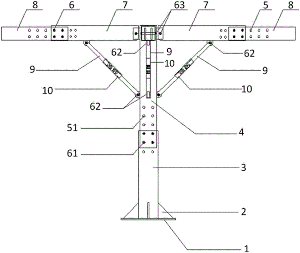
[0020] Please refer to figure 1 , figure 1 It is a schematic diagram of the overall structure of a specific embodiment provided by the present invention.

[0021] In a specific embodiment provided by the present invention, the support frame suitable for pouring floors mainly includes columns 3 and several support beams 7 .

[0022] Generally, four support beams 7 can be designed, that is, four support beams 7 arranged perpendicularly to each other. And each...


PUM


Abstract

The invention discloses a supporting frame applicable to a poured floor. The supporting frame comprises a stand column and a plurality of supporting frames which are connected to the top of the stand column and are used for forming stable supporting on a template of a floor to be poured. In a pouring construction process, a constructor fixes a bottom end of the stand column on the ground, and each supporting frame connected onto the top of the stand column is in contact with the template of the floor to be poured, so that stable supporting is formed and pouring construction is started. Compared with an existing floor pouring manner that a lot of steel pipes or raw woods are needed and are used for supporting the poured floor, each supporting beam connected with the top of the stand column is used for stably supporting the poured floor; only one stand column needs to be erected between the template of the floor to be poured and the ground, and a lot of supporting parts including the steel pipes are not needed, so that the utilization quantity of the supporting parts is greatly reduced, and a lot of spaces are vacated; and meanwhile, the space utilization rate is improved, so that other work types can be carried out in the space and the building construction efficiency is improved.

Description

technical field [0001] The invention relates to the technical field of building construction, in particular to a support frame suitable for pouring floor slabs. Background technique [0002] With the growth of the national economy, the rapid development of urbanization, and the continuous expansion of cities, more and more buildings are used to carry the needs of urbanization development. [0003] At present, all kinds of buildings are usually constructed by pouring concrete, which generally includes pouring columns, pouring beams and pouring stairs. Among them, in the process of pouring concrete on the floor of a building, steel pipes or logs are used as formwork supports. During the construction process of floor slabs, a large number of steel pipes or logs are needed to support the pouring formwork. Smaller, when the area of ​​the pouring floor slab is large, steel pipes or logs need to be densely arranged to support the pouring formwork. At this time, the entire construc...

Claims


Application Information

Patent Timeline
IPC IPC(8): E04G25/06
CPCE04G25/061
Inventor 赵若衡
Owner APCE DESIGN
Learn More