
Locking device suitable for piston rod

A technology of locking device and piston rod, which is applied in the direction of fluid pressure actuating device, etc., to avoid excessive pressing force, reduce material consumption, and save cost.

Inactive Publication Date: 2017-03-22
泸州长江液压密封件有限公司
View PDF6 Cites 0 Cited by
  • Summary
  • Abstract
  • Description
  • Claims
  • Application Information

AI Technical Summary

Problems solved by technology

Therefore, the object of the present invention is to provide a hydraulic cylinder that uses a spring to realize self-locking, to solve the problem of how to make the hydraulic cylinder withstand the external load stably for a long time without any displacement and lock the extended length of the piston rod when the movement stops

Method used


Image

  • Locking device suitable for piston rod
  • Locking device suitable for piston rod
  • Locking device suitable for piston rod

Examples


Embodiment 1

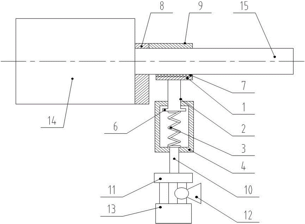
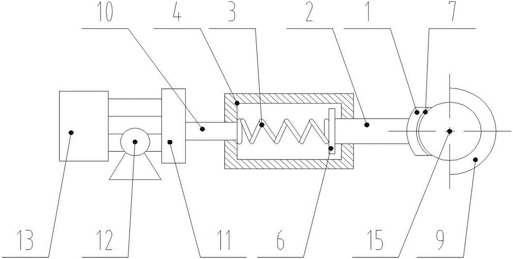
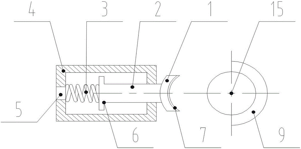
[0024] Such as Figure 1-Figure 3 As shown, the present invention is suitable for a piston rod locking device, including a top plate 1, a push rod 2, a spring 3, a working cylinder 4 and a hydraulic drive system; the push rod 2 is located in the working cylinder 4, and the push rod 2 One end penetrates through one end surface of the working cylinder 4 and is connected to the top plate 1, the other end of the push rod 2 is connected to the spring 3, and the end of the spring 3 away from the push rod 2 is connected to the other end of the working cylinder 4; An oil hole 5 is provided on the end surface of the working cylinder 4 connected with the spring 3, and the hydraulic drive system delivers pressure oil to the working cylinder 4 or draws out the oil through the oil hole 5. The clamping plate 1 is located on one side of the piston rod 15 of the hydraulic cylinder 14. When the hydraulic drive system sends pressure oil into the working cylinder 4, the push rod 2 moves to the t...


PUM


Abstract

The invention discloses a locking device suitable for a piston rod. The locking device comprises a push plate, a push rod, a spring, a working cylinder and a hydraulic driving system. The push rod is located in the working cylinder. One end of the push rod penetrates through one end face of the working cylinder and then is connected with the push plate. The other end of the push rod is connected with the spring. The end, far from the push rod, of the spring is connected with the other end face of the working cylinder. An oil hole is formed in the end face, connected with the spring, of the working cylinder. The hydraulic driving system delivers hydraulic oil into the working cylinder through the oil hole or pumps oil out through the oil hole. The push plate is located on the side provided with a piston rod of a hydraulic cylinder. When the hydraulic driving system delivers hydraulic oil into the working cylinder, the push rod moves towards the push plate under the action of hydraulic oil. The push plate moves towards the piston rod and pushes the sidewall of the piston rod under the action of the push rod. Accordingly, the piston rod is locked.

Description

Technical field [0001] The invention relates to a woodworking tool, in particular to a locking device suitable for a piston rod. Background technique [0002] The hydraulic cylinder is a hydraulic actuator that converts hydraulic energy into mechanical energy and performs linear reciprocating motion (or swing motion). It has simple structure and reliable work. When it is used to achieve reciprocating motion, the deceleration device can be eliminated, and there is no transmission gap, and the motion is stable. Therefore, it is widely used in various mechanical hydraulic systems. The output force of the hydraulic cylinder is proportional to the effective area of ​​the piston and the pressure difference between its two sides; the hydraulic cylinder is basically composed of a cylinder barrel and a cylinder head, a piston and a piston rod, a sealing device, a buffer device and an exhaust device. The hydraulic cylinder is an actuator that drives and bears a large load. It is usually ...

Claims


Application Information

Patent Timeline
Patent Type & Authority Applications(China)
IPC IPC(8): F15B15/26
CPCF15B15/262F15B2015/268
Inventor 袁祖辉何运清李代军徐华明颜新东黄俊明
Owner 泸州长江液压密封件有限公司
Learn More