
Stamping and connecting part structure for lateral expansion locating slot

A stamping connection and lateral expansion technology, applied in the direction of fixing devices, mechanical equipment, etc., can solve the problems of not easy to make mistakes, high installation cost, and small technical constraints, and achieve the effect of low cost, firm assembly, and flexible selection

Inactive Publication Date: 2017-03-22
SUZHOU ZZH INTPROP SERVICES
View PDF8 Cites 0 Cited by
  • Summary
  • Abstract
  • Description
  • Claims
  • Application Information

AI Technical Summary

Problems solved by technology

[0002] When assembling gorgeous and beautiful appearance objects on the complex shape skeleton model built, the assembly is very particular about the process and sequence. If one step makes a mistake, many steps are required to compensate. If a defect occurs in one place, many related parts need to be disassembled. , Time-consuming, labor-intensive, not free, prone to error and accidental damage, requires skilled and prioritized technical individuals to install correctly and efficiently, and the installation cost is also high. The society urgently needs to be fast, convenient, with small technical constraints, and not easy to make mistakes. It is easy to correct mistakes, and you can install and assemble gorgeous and beautiful appearance objects by yourself without training proficiency.

Method used


Image

  • Stamping and connecting part structure for lateral expansion locating slot
  • Stamping and connecting part structure for lateral expansion locating slot
  • Stamping and connecting part structure for lateral expansion locating slot

Examples


Embodiment Construction

[0026] The present invention will be described in detail below with reference to the accompanying drawings and in combination with embodiments.

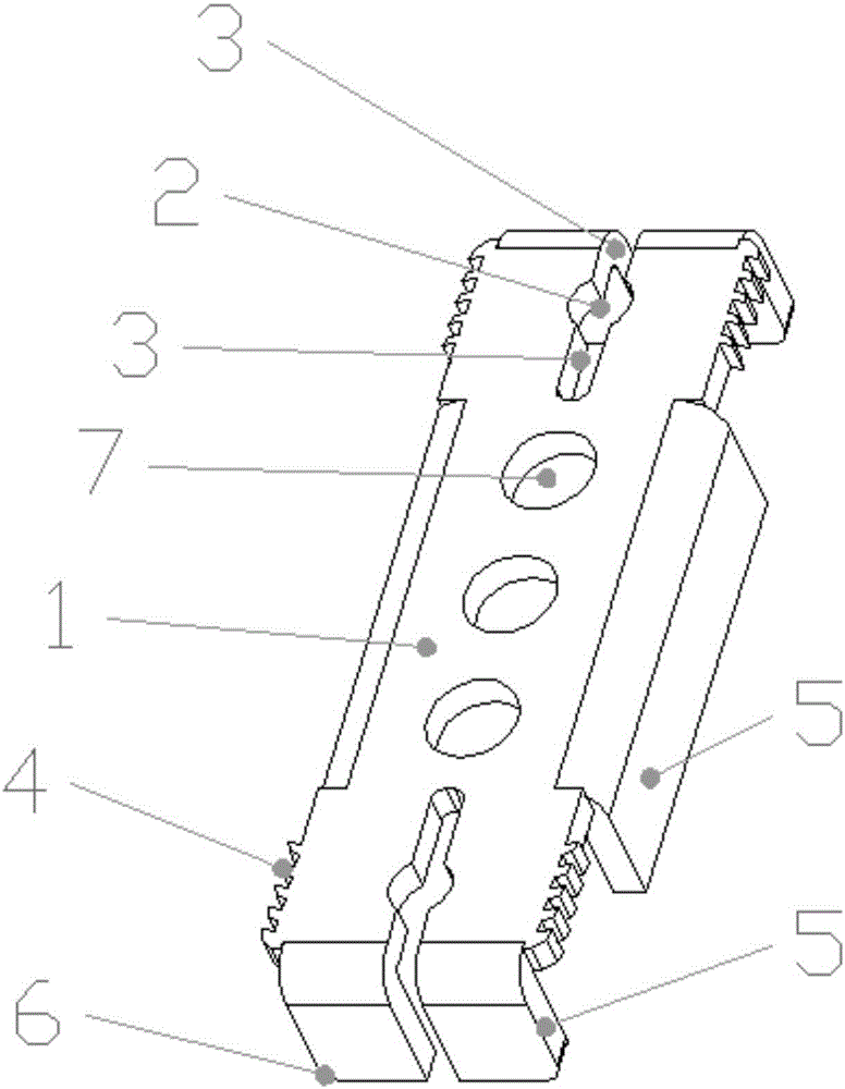
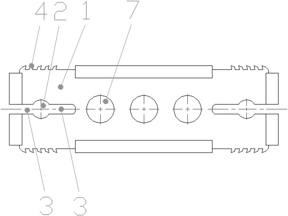
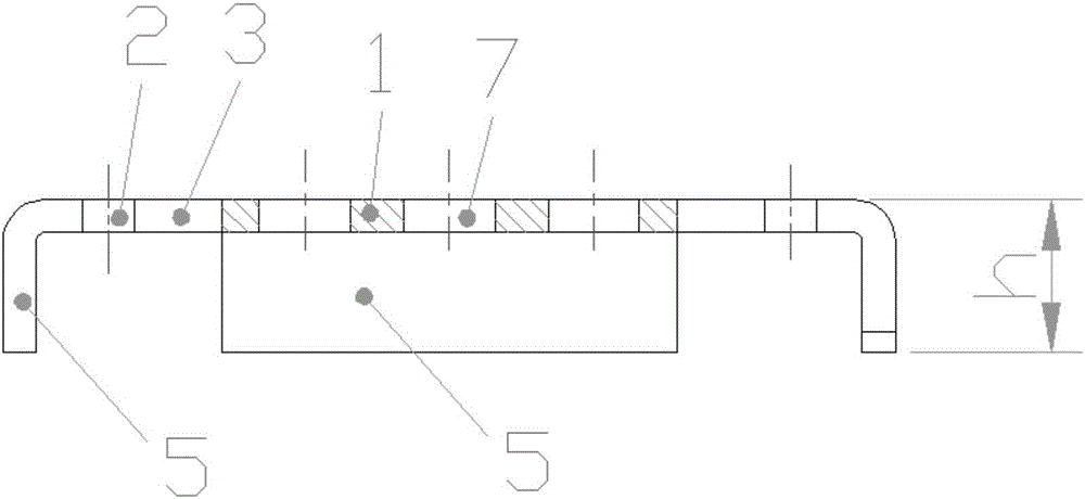
[0027] refer to Figure 1 to Figure 5 As shown, a stamping connector structure for a lateral expansion positioning groove, a stamping connector structure for a lateral expansion positioning groove, including a stamping part structure 1, and the stamping part structure 1 is provided with a height-controlling hamstring group 5. The jamming pawl group 4, the extrusion hole 2 and the extrusion elastic groove 3, the jamming pawl group 4 is a group opposite to each other, and is located on both sides of the long side of the stamping part structure 1. The expansion hole 2 is located in the middle of a group of clamping pawl groups 4, the expansion elastic groove 3 is located on both sides of the expansion hole 2, and runs through the expansion hole 2, and the stamping part structure 1 is also provided with a circumscribed The installation ...


PUM


Abstract

The invention discloses a stamping and connecting part structure for a lateral expansion locating slot. The stamping and connecting part structure comprises a stamping part structural body; the stamping part structural body is provided with height-controlled hamstring groups, clamping and binding pawl groups, extrusion expansion holes and elastic extrusion expansion slots; every two clamping and binding pawls are opposite to form a group, and the lamping and binding pawl groups are located on two side edges at the long side of the stamping part structural body; each of the extrusion expansion holes is located in the middle of one of the lamping and binding pawl groups; the elastic extrusion expansion slots are located in two sides of each extrusion expansion hole and pass through each extrusion expansion hole; the elastic extrusion expansion slots are longer than the clamping and binding pawl groups; and externally-connected mounting holes are also formed in the stamping part structural body so as to be conveniently connected with other parts. The stamping and connecting part structure is low in cost, convenient to machine, suitable for extra-large-batch automatic production, flexible in selective purchasing, simple and rapid in operation during use, firm and reliable in disassembly and assembly, capable of reducing waste because of reuse and wide in application range and is an ideal accessory for producing and assembling furniture, exhibition stands and articles such as indoor and outdoor decoration goods by using a slot-containing structural member, and all parts are not easily damaged.

Description

technical field [0001] The invention relates to the field of frame assembly accessories, in particular to a stamping connector structure for a lateral expansion positioning groove. Background technique [0002] When assembling gorgeous and beautiful appearance objects on the complex shape skeleton model built, the assembly is very particular about the process and sequence. If one step is wrong, many steps are required to compensate. If a defect occurs in one place, many related parts need to be disassembled. , Time-consuming, labor-intensive, not free, prone to error and accidental damage, requires skilled and prioritized technical individuals to install correctly and efficiently, and the installation cost is also high. The society urgently needs to be fast, convenient, with small technical constraints, and not easy to make mistakes. It is also convenient to correct mistakes, and the method and means of installing and assembling gorgeous and beautiful appearance objects can ...

Claims


Application Information

Patent Timeline
Patent Type & Authority Applications(China)
IPC IPC(8): F16B1/00
CPCF16B1/00
Inventor 征茂德陈巧云征建高
Owner SUZHOU ZZH INTPROP SERVICES
Learn More