
Circuit board detection apparatus with light source module with light insulation function

A technology of light source components and detection devices, which is applied to measurement devices, optical devices, instruments, etc., can solve problems such as affecting detection, affecting the accuracy of picture information, affecting detection accuracy, etc., to achieve consistent conveying direction, clear shooting effect, and improved detection. The effect of precision

Inactive Publication Date: 2017-03-22
佛山市坦斯盯科技有限公司 +1
View PDF8 Cites 4 Cited by
  • Summary
  • Abstract
  • Description
  • Claims
  • Application Information

AI Technical Summary

Problems solved by technology

[0003] When the existing online optical detector detects, the PCB board is placed on a flat plate, one surface of the PCB board is detected first, and then the PCB board is turned over to detect the other surface of the PCB board, so that the PCB board cannot be detected at the same time. Two surfaces, resulting in low detection efficiency; in addition, due to slight bending of the tested part, insufficient light intensity of the light source and shadow areas, etc., this will affect the accuracy of the acquired image information, thereby affecting Detection accuracy
[0004] The light source assembly is usually fixed on the rack to illuminate the circuit board, so that the brightness on the surface of the circuit board is sufficient for the camera module to capture a clear image for comparison detection. Often the clearer the captured image, the more accurate the detection result; but due to The surface of the circuit board is uneven, so there will be shadows that affect the detection in the captured image

Method used


Image

  • Circuit board detection apparatus with light source module with light insulation function
  • Circuit board detection apparatus with light source module with light insulation function
  • Circuit board detection apparatus with light source module with light insulation function

Examples


Embodiment Construction

[0030] The technical solutions of the present invention will be further described below in conjunction with the accompanying drawings and through specific implementation methods.

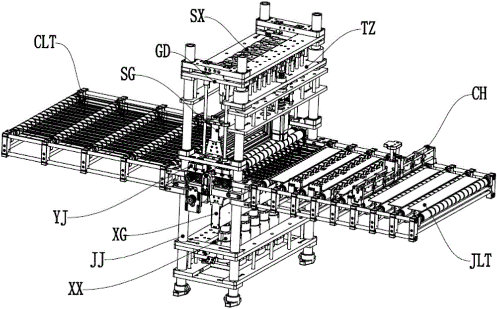
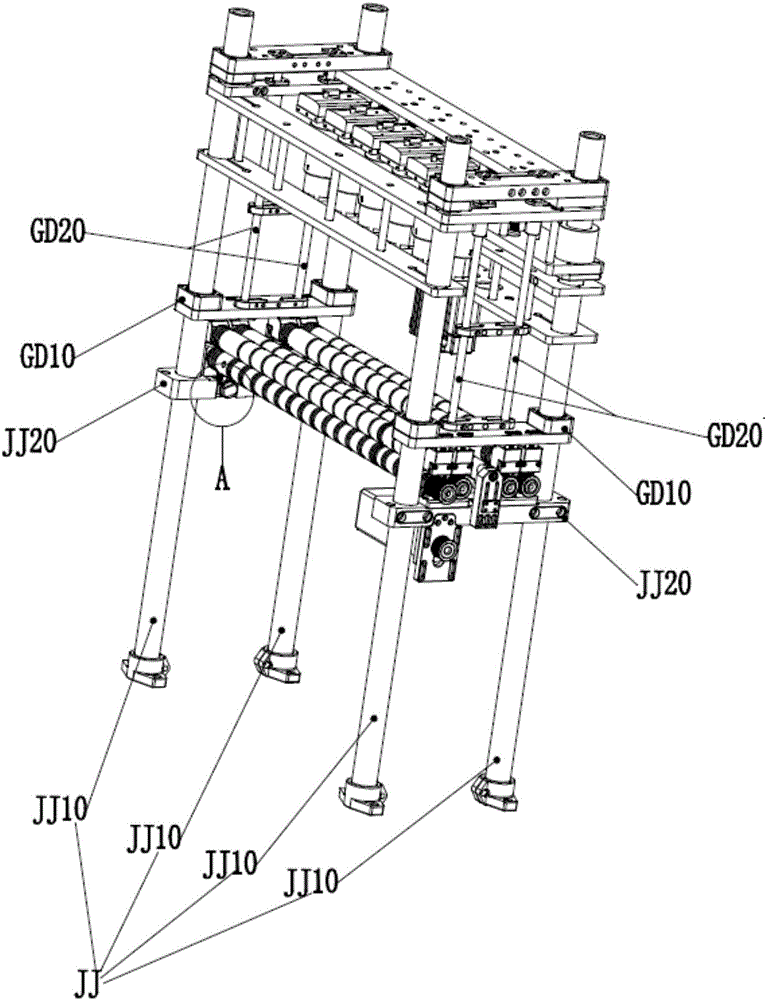
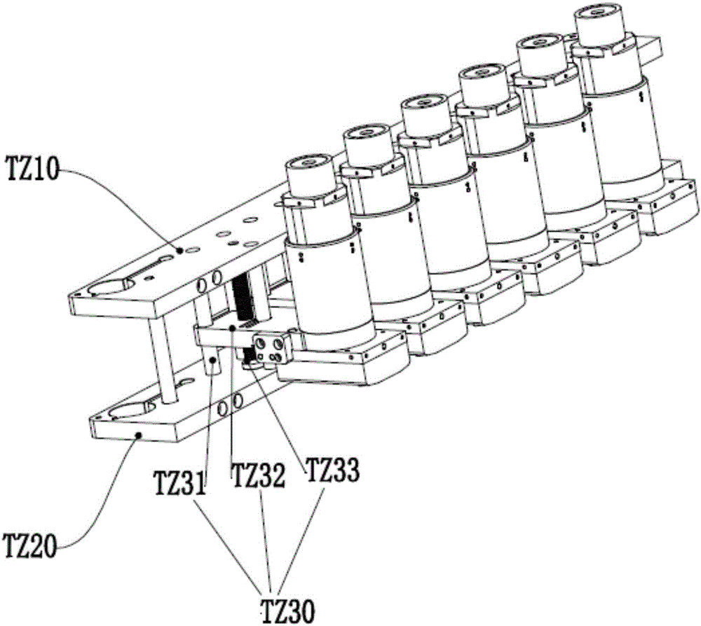
[0031] Such as Figure 1-11 As shown, a circuit board detection device with a light source assembly having a light-isolation function includes a frame JJ, a camera module, a light source module and a roller pressing module YJ; the upper and lower sides of the roller pressing module are both A camera module and a light source module are provided; the frame JJ is a frame composed of no less than four columns JJ10, and the frame JJ is sequentially composed of a lower camera module XX, a lower light source module XG, The roller pressing module YJ, the upper light source module SG and the upper camera module SX; the lower light source module XG and the lower camera module XX are fixed on the frame JJ, and the upper camera module The lenses of SX and the lower camera module XX all face the roller pressin...


PUM


Abstract

The invention relates to the field of circuit board detection and specially relates to a circuit board detection apparatus with a light source module with a light insulation function. The apparatus comprises a frame, a camera module, the light source module and a roller compaction module, wherein the light source module comprises a lamp box and a lamp strip assembly; the lamp box comprises two lamp box side plates, the lamp box comprises lamp box plates which are fixedly installed in tandem between the two lamp box side plates, the lamp box further comprises two top lamp strips fixedly installed at the top portion of the lamp box, and a viewing gap used for viewing of the camera module is reserved between the two top lamp strips; the lamp strip assembly comprises lamp strip side plates, a lamp strip group is fixedly installed between the lamp strip side plates, and the lamp strip group is provided with multiple lamp strips; and the lamp box side plates and the lamp strip side plates are fixedly assembled.

Description

technical field [0001] The invention relates to the field of circuit board detection, in particular to a circuit board detection device with a light source component having a light-isolation function. Background technique [0002] The on-line optical detector is an advanced on-line inspection technology. It obtains the image information of the surface of the tested part and compares it with the image information of the qualified part to detect whether the tested part is qualified. At present, online optical detectors are used in a wide range of fields, such as to detect PCB boards (printed circuit boards). Due to the complexity of PCB boards, more and more design circuits, and more and more layers, online optical detectors are used The detector to detect the PCB board is far more mature and efficient than the manual detection method, which is more conducive to ensuring the detection accuracy and controlling the product quality. [0003] When the existing online optical dete...

Claims


Application Information

Patent Timeline
IPC IPC(8): G01B11/06
CPCG01B11/06
Inventor 陈新何桢刘冠峰楚伟
Owner 佛山市坦斯盯科技有限公司
Learn More