Method and device for monitoring exercise status
A motion state and monitoring device technology, which is applied in measuring devices, surveying and navigation, and speed measurement using acceleration, etc., can solve the problems of inability to monitor motion state, GPS error, and high cost of GPS, so as to realize calculation and display, improve The effect of using versatility and optimizing user experience
- Summary
- Abstract
- Description
- Claims
- Application Information
AI Technical Summary
Problems solved by technology
Method used
Image
Examples
Embodiment 1
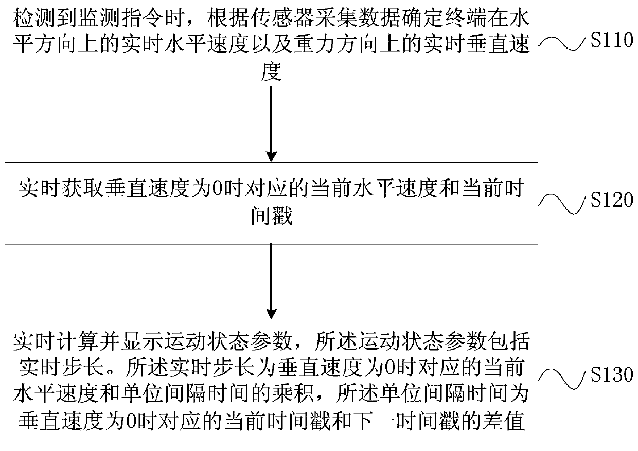
[0027] figure 1 It is a schematic flow chart of an exercise state monitoring method provided in Embodiment 1 of the present invention. This embodiment is applicable to the situation of monitoring the exercise state. The method can be executed by an exercise state monitoring device, which can be implemented by hardware and / or It is composed of software and can generally be integrated into a terminal. The terminal can be a smart phone, a wearable device (such as a smart bracelet, a smart watch), etc., or a combination of a smart phone and a wearable device, that is, the sensor collected by the wearable device Corresponding data and simple calculations are performed, and more complex calculations are performed and displayed by the smartphone.
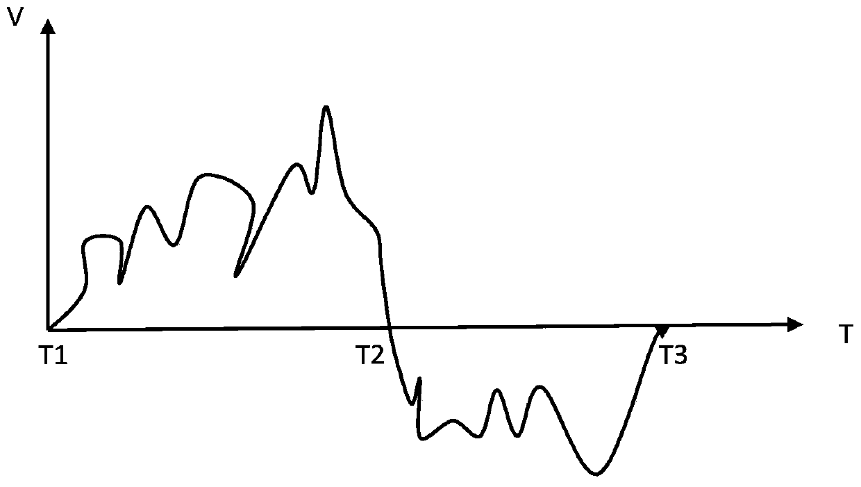
[0028] Among them, the application principle of this method is that when the user wears the terminal for exercise, he usually wears the terminal on his hand or puts it in his pocket, regardless of whether the terminal is worn on his hand o...
Embodiment 2
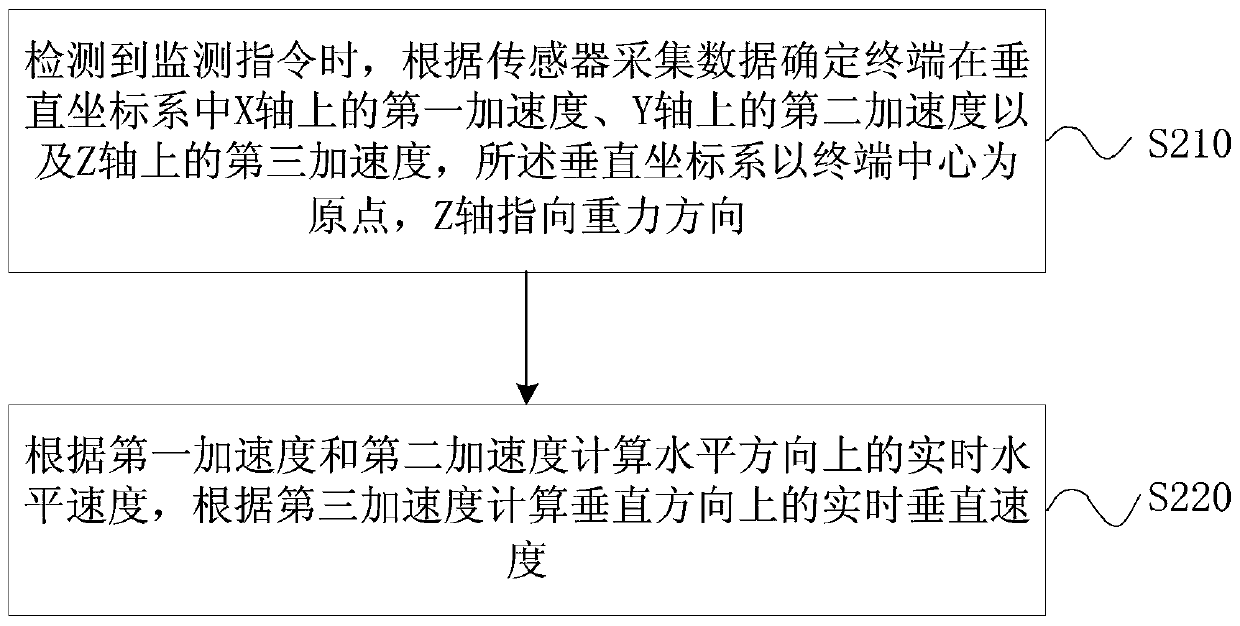
[0043] figure 2 It is a schematic flow chart of a motion state monitoring method provided by Embodiment 2 of the present invention. On the basis of the above embodiments, this embodiment preferably determines that the terminal is in the horizontal direction according to the data collected by the sensor when the monitoring instruction is detected. The real-time horizontal speed and the real-time vertical speed in the direction of gravity are further optimized, including:
[0044] S210. When the monitoring instruction is detected, determine the first acceleration on the X axis, the second acceleration on the Y axis, and the third acceleration on the Z axis of the terminal in the vertical coordinate system according to the data collected by the sensor. The vertical coordinate system is based on the terminal The center is the origin, and the Z-axis points to the direction of gravity.
[0045] Specifically, the real-time acceleration component of the terminal in the three-dimensi...
Embodiment 3
[0050] image 3 It is a schematic flowchart of a motion state monitoring method provided by Embodiment 3 of the present invention. On the basis of the above embodiments, this embodiment preferably determines that the terminal is in the vertical coordinate system according to the data collected by the sensor when a monitoring command is detected. The first acceleration on the X axis, the second acceleration on the Y axis, and the third acceleration on the Z axis are further optimized, including:
[0051] S310. When the monitoring instruction is detected, collect the real-time acceleration components of the terminal on three axes in its own three-dimensional coordinate system according to the three-axis acceleration sensor, and determine the direction of gravity according to the data collected by the gyroscope sensor.
[0052] Among them, the three-axis acceleration sensor The three-axis acceleration sensor works based on the basic principle of acceleration, and has the characte...
PUM
 Abstract
Description
Claims
Application Information
 - R&D
- Intellectual Property
- Life Sciences
- Materials
- Tech Scout
- Unparalleled Data Quality
- Higher Quality Content
- 60% Fewer Hallucinations
Browse by: Latest US Patents, China's latest patents, Technical Efficacy Thesaurus, Application Domain, Technology Topic, Popular Technical Reports.
© 2025 PatSnap. All rights reserved.Legal|Privacy policy|Modern Slavery Act Transparency Statement|Sitemap|About US| Contact US: help@patsnap.com


