
Vibration analysis device

一种振动分析、振动周期的技术,应用在分析材料、测量装置、测量振动等方向,能够解决难以计算工具振动的周期、条纹边界间隔不均匀等问题

Active Publication Date: 2017-03-22
FANUC LTD
View PDF8 Cites 4 Cited by
  • Summary
  • Abstract
  • Description
  • Claims
  • Application Information

AI Technical Summary

Problems solved by technology

In this case, there is a problem that the interval of the fringe boundary is not uniform, and it is difficult to calculate the period of vibration of the tool relative to the workpiece

Method used


Image

  • Vibration analysis device
  • Vibration analysis device
  • Vibration analysis device

Examples


Embodiment Construction

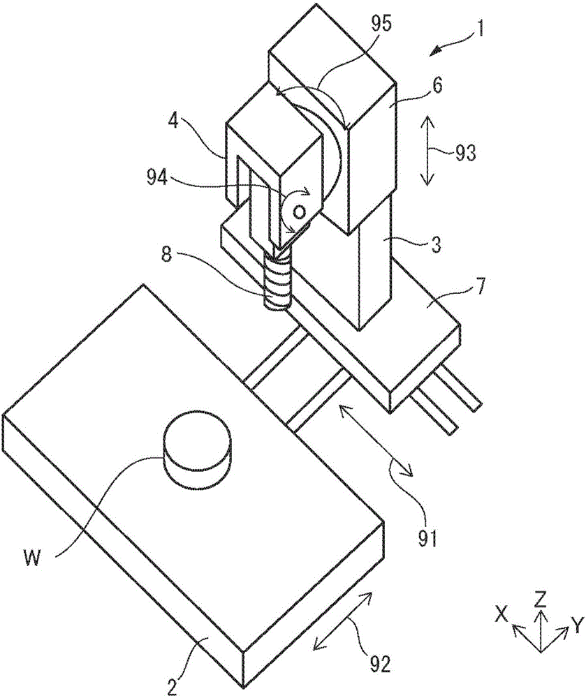
[0029] Reference Figure 1 to Figure 17 The vibration analysis device in the embodiment will be described. The vibration analysis device of the present embodiment calculates the vibration period when the tool vibrates with respect to the workpiece during the processing of the workpiece by the machine tool.

[0030] figure 1 It is a perspective view of the machine tool of this embodiment. In this embodiment, a numerical control type machine tool 1 having five drive shafts is illustrated and described. The machine tool 1 includes a base 7 and a table 2, and the workpiece W is fixed to the table 2. The machine tool 1 includes a support column 3 fixed to a base 7. The machine tool 1 includes a support member 6 that moves in the direction indicated by an arrow 93 with respect to the pillar 3 and a head 4 supported by the support member 6. The tool 8 is supported by the head 4.

[0031] The machine tool 1 includes a driving device that changes the relative position and posture of the...


PUM


Abstract

A vibration analysis device calculates a vibration cycle which occurs during a period in which a workpiece is processed by a machine tool, and includes a tangential velocity calculation unit which calculates a velocity in a tangential direction of a movement path of a processing point by using positional information of a drive axis. The vibration analysis device comprises a movement distance calculation unit which calculates a first movement distance of the processing point on the movement path by using the velocity in the tangential direction. The vibration analysis device comprises a vibration cycle calculation unit which calculates a vibration cycle corresponding to streaks on the basis of previously measured streak intervals on the workpiece and the first movement distance of the processing point.

Description

Technical field [0001] The invention relates to a vibration analysis device for calculating the period of vibration of a tool relative to a workpiece. Background technique [0002] The machine tool can perform machining while moving at least one of the workpiece (workpiece) and the tool along a predetermined drive shaft. That is, the machine tool can perform machining while changing the relative position of the workpiece and the tool. During the processing period, the relative position of the tool with respect to the workpiece changes. Therefore, it is preferable that the operator can grasp the processing state such as the speed of the tool with respect to the workpiece. [0003] Japanese Patent No. 5302371 discloses a numerical control device for a machine tool having the function of displaying physical data of the speed of the drive shaft of the machine tool and the representative point of the tool based on the moving distance of the tool. The following is disclosed: In this de...

Claims


Application Information

Patent Timeline
Patent Type & Authority Applications(China)
IPC IPC(8): G01H17/00G01M13/00
CPCG01H17/00G01M13/00G01H3/00G01M7/00G01N29/04G01N29/12G01N29/4454G01N29/4472
Inventor 小川肇手塚淳一
Owner FANUC LTD
Features
  • Generate Ideas
  • Intellectual Property
  • Life Sciences
  • Materials
  • Tech Scout
  • Unparalleled Data Quality
  • Higher Quality Content
  • 60% Fewer Hallucinations
Learn More