Method and device for monitoring gas turbine gas path performance

A gas turbine and gas path technology, applied in the direction of internal combustion engine testing, etc., can solve problems such as failure to effectively find gas path failures

Active Publication Date: 2017-03-22
PIPECHINA SOUTH CHINA CO
View PDF8 Cites 7 Cited by
  • Summary
  • Abstract
  • Description
  • Claims
  • Application Information

AI Technical Summary

Problems solved by technology

[0006] In order to solve at least one of the above-mentioned technical problems, the present invention provides a method and device for monitoring

Method used


Image

  • Method and device for monitoring gas turbine gas path performance
  • Method and device for monitoring gas turbine gas path performance
  • Method and device for monitoring gas turbine gas path performance

Examples


Embodiment 1

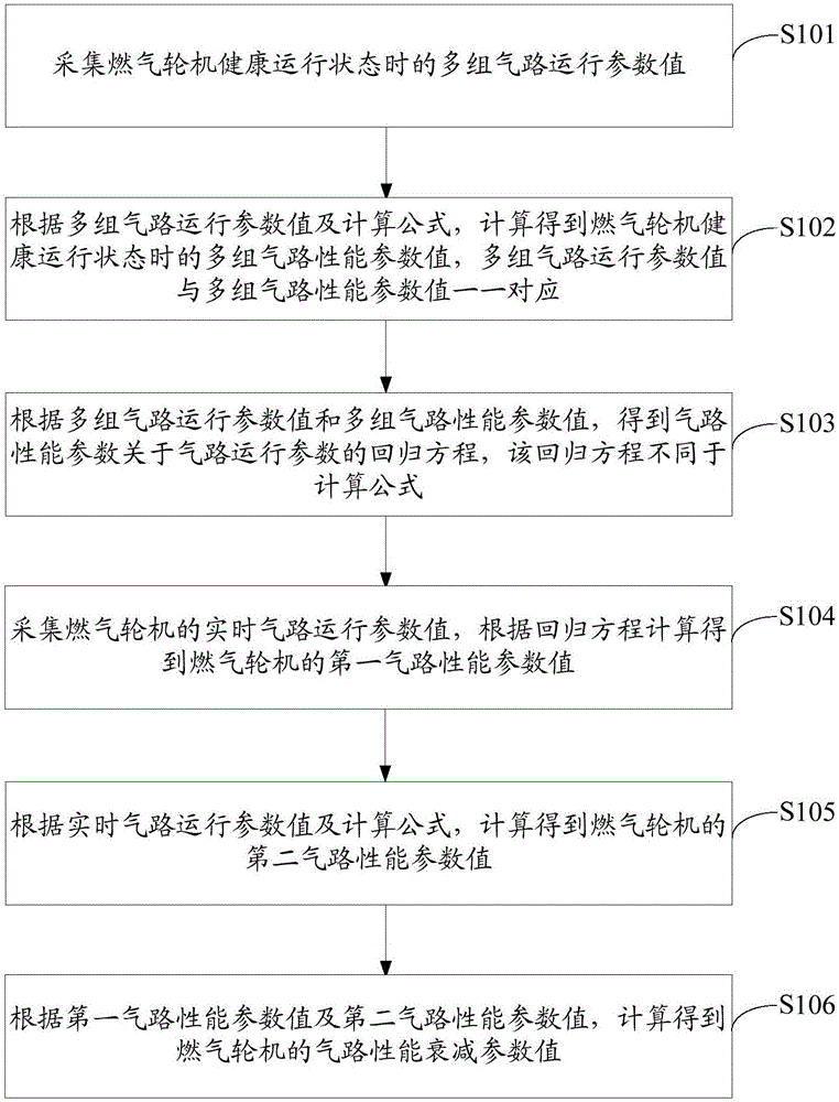
[0095] This embodiment provides a method for monitoring the gas path performance of a gas turbine, such as figure 1 As shown, steps S101, S102, S103, S104, S105 and S106 are included. Each step is described in detail below.

[0096] Step S101: Collect multiple sets of gas path operating parameter values ​​when the gas turbine is in a healthy operating state.

[0097] Gas path operating parameters include data directly measured by sensors installed on various components of the gas turbine, or parameters that cannot be directly measured but can be directly measured by sensors and obtained after a basic operation. Specifically, the operating parameters of the gas circuit may include ambient temperature, ambient pressure, gas generator compressor inlet temperature, gas generator compressor outlet temperature, gas generator compressor inlet pressure, gas generator compressor outlet pressure, gas generator Compressor rotor speed, gas generator turbine inlet temperature, gas genera...

Embodiment 2

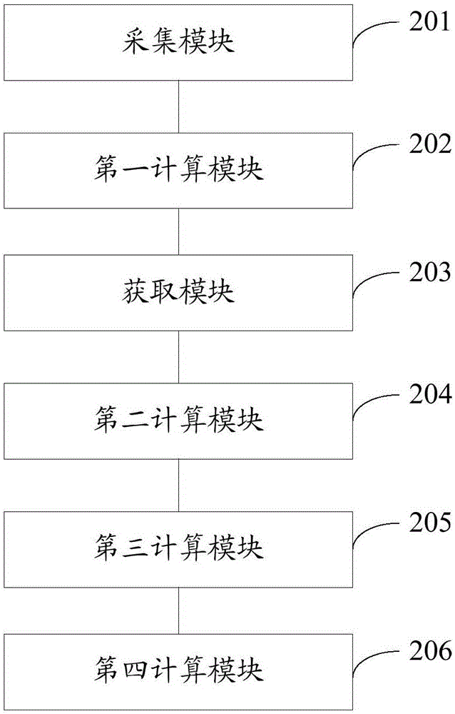
[0278] Corresponding to Embodiment 1, this embodiment provides a device for monitoring the gas path performance of a gas turbine, such as figure 2 As shown, it includes a collection module 201 , a first calculation module 202 , an acquisition module 203 , a second calculation module 204 , a third calculation module 205 and a fourth calculation module 206 . Each module is introduced in detail below.

[0279] The collection module 201 is used to collect multiple groups of gas circuit operation parameter values ​​when the gas turbine is in a healthy operation state.

[0280] The gas circuit operating parameters collected by the collection module 201 include data directly measured by sensors installed on various components of the gas turbine, or parameters that cannot be directly measured but can be directly measured by sensors after a basic operation. Specifically, the operating parameters of the gas path include ambient temperature, ambient pressure, gas generator compressor i...


PUM


Abstract

The invention provides a method and a device for monitoring gas turbine gas path performance. The method comprises steps: operation parameter values of multiple groups of gas paths when the gas turbine is in a healthy operation state are acquired; according to the operation parameter values of multiple groups of gas paths and a calculation formula, performance parameter values of multiple groups of gas paths in one-to-one correspondence with the operation parameter values of multiple groups of gas paths are obtained through calculation; on the basis, a regression equation, different from the calculation formula, for the gas path performance parameters relative to the gas path operation parameters is obtained; the real-time gas path operation parameter values of the gas turbine are acquired, and a first gas path performance parameter value is obtained according to the regression equation; according to the real-time gas path operation parameter values of the gas turbine and a calculation formula, a second gas path performance parameter value is obtained through calculation; and according to the first gas path performance parameter value and the second gas path performance parameter value, the gas path performance attenuation parameter value of the gas turbine is obtained through calculation. The method and the device provided by the invention can timely and effectively detect fault of the gas turbine.

Description

technical field [0001] The invention relates to the technical field of gas turbines, in particular to a method and device for monitoring the gas path performance of a gas turbine. Background technique [0002] Gas turbines can be used in aviation, ships, electric power and other fields that require mechanical drives, and play a very prominent strategic role. The thermal parameters of gas turbines include gas path operation parameters and gas path performance parameters, which can be used to measure the health status of gas turbines. When faults such as blade fouling, blade breakage, and nozzle ablation occur in gas turbine components, it will be reflected in the operating parameters and performance parameters at the corresponding positions. According to the operating parameters and performance parameters of the gas circuit, faults in the early stage of development can be found in time to avoid damage to other components and losses caused by emergency shutdowns. [0003] Ga...

Claims


Application Information

Patent Timeline
IPC IPC(8): G01M15/05
CPCG01M15/05
Inventor 李刚李振林张衍岗谷思宇蔡德宇刘培军刘建臣李世尧
Owner PIPECHINA SOUTH CHINA CO
Why Eureka
Try Eureka