Optical fiber cutting device
An optical fiber and cleaver technology, which is applied in the coupling of optical waveguides, etc., can solve the problems of unsatisfactory cutting effect, the cleaver cannot identify the fiber, and the end face cannot be guaranteed to be flat without tailing, etc., to achieve strong cutting consistency and cutting. High precision and good cutting effect
- Summary
- Abstract
- Description
- Claims
- Application Information
AI Technical Summary
Problems solved by technology
Method used
Image

Examples
Embodiment 1
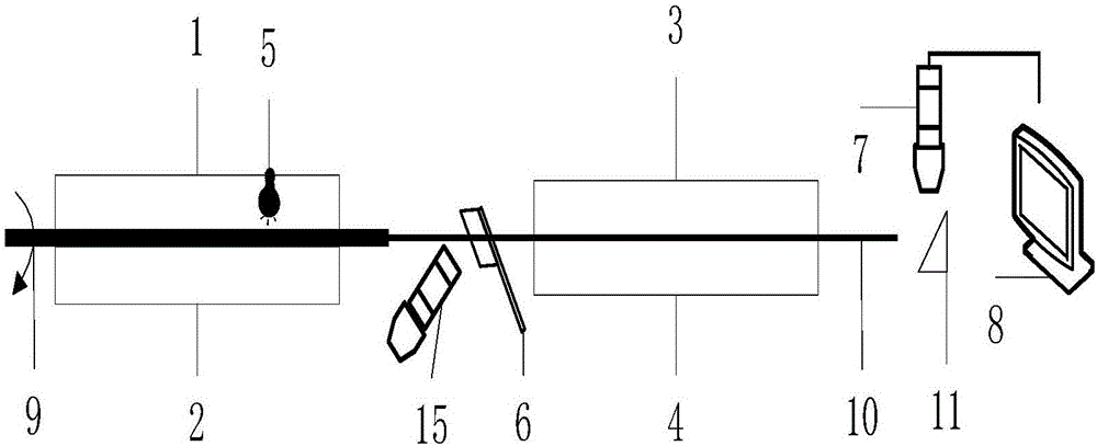
[0050] like figure 1 In the optical fiber cutting equipment shown, it is first necessary to pre-cut the optical fiber before the formal cutting, so that the microscope lens can image the end face, so as to judge the angular position of the stress zone. Among them, the requirement of pre-cutting on the cutting quality is that the fiber end surface structure (such as the stress zone) can be observed; secondly, select the corresponding cutting program, turn on the vacuum suction pump, and absorb the optical fiber after stripping the coating layer on the lower fixture , adjust the focus of the microscope so that the end face is imaged on the monitor; rotate the fiber manually so that the characteristic area of the fiber (such as the stress area) is in a horizontal or vertical symmetrical position relative to the cutting edge of the cutting knife; measure the diameter of the fiber with a digital micrometer Push it to the corresponding position so that the end face of the micromet...
Embodiment 2
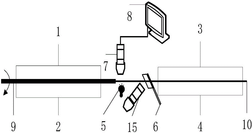
[0054] like figure 2 , 3 The optical fiber cutting equipment shown does not need to pre-cut the optical fiber. However, it is necessary to ensure that the cutting direction of the diamond cutter is strictly perpendicular to the central visual axis of the microscope lens. After selecting the corresponding cutting program, turn on the vacuum suction pump, absorb the optical fiber after stripping the coating layer on the lower fixture, adjust the focus of the microscope, and make the optical fiber image on the side of the display; rotate the optical fiber manually to make the side features of the optical fiber Into a specific symmetrical distribution, that is, the optical fiber characteristic area (stress area) is in a horizontal or vertical symmetrical position relative to the cutting edge of the cutting knife, and the rest are the same as in Embodiment 1.
[0055] After testing, for the same optical fiber (such as PLMA-20 / 400 Panda), the polarization-maintaining optical fibe...
Embodiment 3
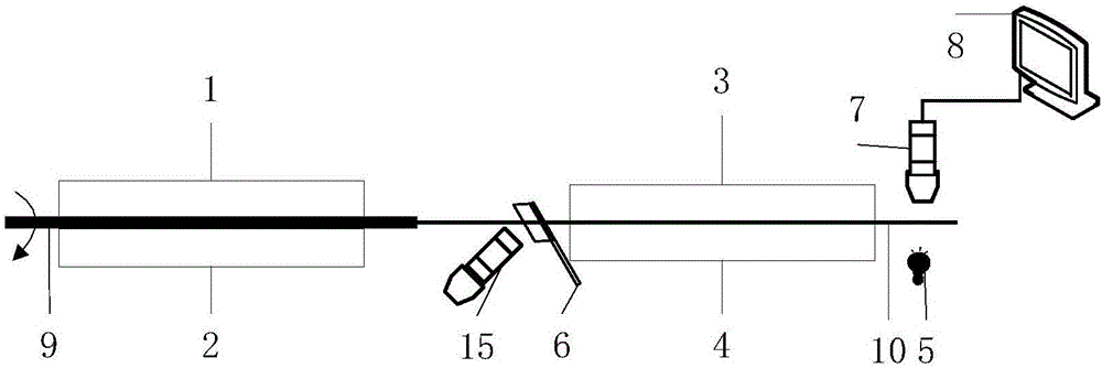
[0057] like Figure 5 As shown, the high-precision stepping motor drives the left clamp to rotate with the center of the optical fiber to be cut as the strict axis, so that the left clamp of the cleaver has a rotation function of 180° or more than 360°, which is used to replace manual rotation. Both the end face observation in embodiment 1 and the side image recognition in embodiment 2 can match the corresponding recognition and self-learning functions according to the images to complete the automatic rotation of the optical fiber. High-precision stepping motor drive can make the angular position of the fiber stress zone more accurate and stable. The cutting effect with cutting angle less than 0.2°, no tailing, no chipping or knife edge can be obtained. Wherein, the right clamp can be closed and then rotate together with the left clamp. All the other are with embodiment 1 or 2.
PUM
 Abstract
Description
Claims
Application Information