
Organic light-emitting pixel driving circuit, driving method and organic light-emitting display panel

A pixel driving circuit and organic technology, applied in the field of organic light-emitting pixel driving circuits and organic light-emitting display panels, can solve the problems of poor uniformity of display brightness of organic light-emitting panels, poor uniformity of driving tubes, different driving currents, etc., and improve display uniformity. , The drive current is uniform, and the effect of threshold compensation is realized.

Active Publication Date: 2017-03-22
WUHAN TIANMA MICRO ELECTRONICS CO LTD
View PDF10 Cites 39 Cited by
  • Summary
  • Abstract
  • Description
  • Claims
  • Application Information

AI Technical Summary

Problems solved by technology

Due to the limitations of the manufacturing process, especially the threshold voltage |Vth| of the drive tube made of low-temperature polysilicon technology is very poor and has drift, resulting in different drive currents when the same gray-scale voltage is input
The inconsistency of the driving current makes the working state of the organic light-emitting element unstable, resulting in poor uniformity of display brightness of the organic light-emitting panel

Method used


Image

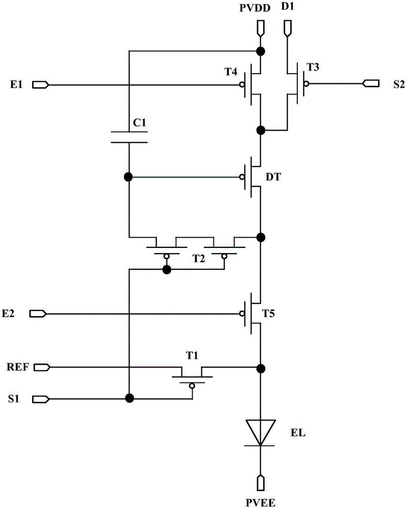
  • Organic light-emitting pixel driving circuit, driving method and organic light-emitting display panel
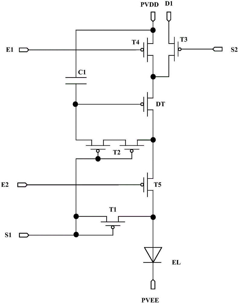
  • Organic light-emitting pixel driving circuit, driving method and organic light-emitting display panel
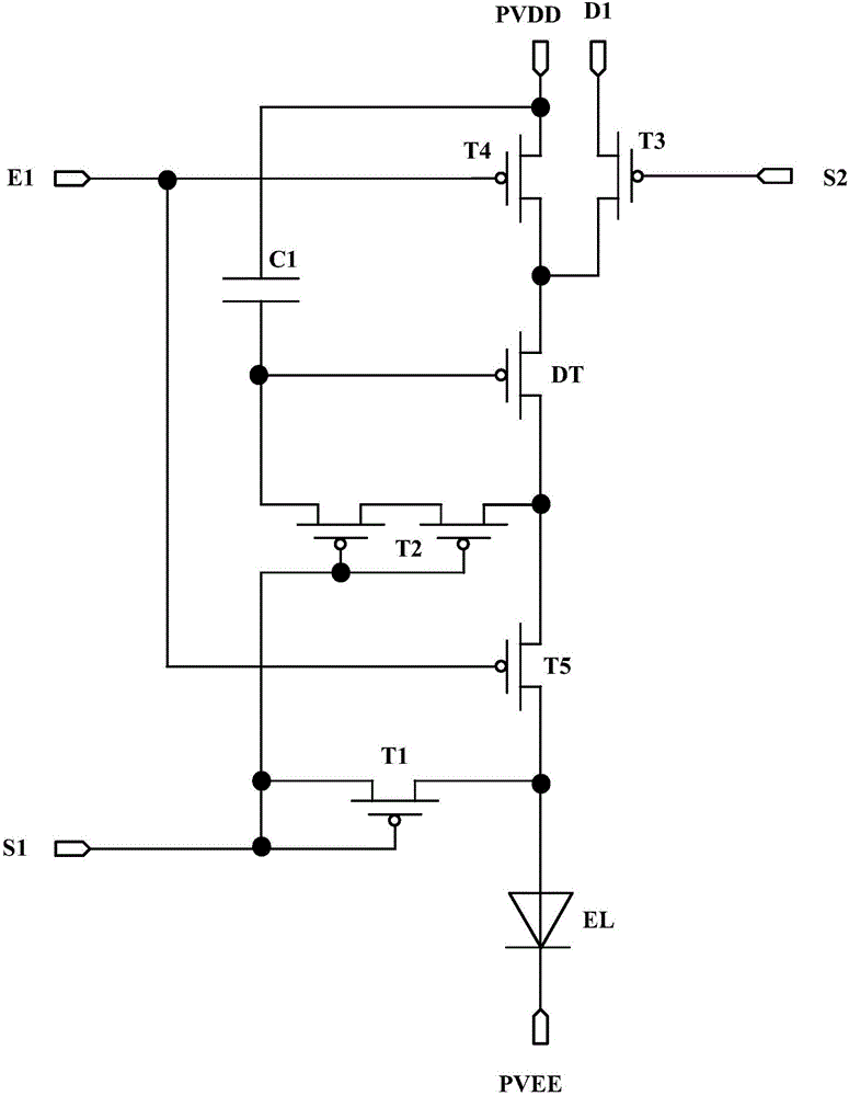
  • Organic light-emitting pixel driving circuit, driving method and organic light-emitting display panel

Examples


Embodiment Construction

[0020] The application will be further described in detail below in conjunction with the accompanying drawings and embodiments. It should be understood that the specific embodiments described here are only used to explain related inventions, rather than to limit the invention. It should also be noted that, for ease of description, only parts related to the invention are shown in the drawings.

[0021] It should be noted that, in the case of no conflict, the embodiments in the present application and the features in the embodiments can be combined with each other. The present application will be described in detail below with reference to the accompanying drawings and embodiments.

[0022] see figure 1 Shown is a schematic structural diagram of an embodiment of an organic light-emitting pixel driving circuit of the present application.

[0023] The organic light-emitting pixel driving circuit of the present application includes a first transistor T1, a second transistor T2, ...


PUM


Abstract

The invention discloses an organic light-emitting pixel driving circuit, a driving method thereof and an organic light-emitting display panel. The organic light-emitting pixel driving circuit comprises a first transistor, a second transistor, a third transistor, a fourth transistor, a fifth transistor, a capacitor and a light-emitting element, wherein the first transistor transmits an initialization voltage to the light-emitting element; the second transistor transmits an initialization voltage to a driving transistor and compensates for a threshold voltage of the driving transistor; the third transistor transmits a data signal voltage to the driving transistor; the fourth transistor transmits a first power voltage signal to the driving transistor; the fifth transistor is coupled between the driving transistor and an anode of the light-emitting element in series, and controls the electrical connection between the driving transistor and the anode of the light-emitting element; the capacitor is used for storing the data signal voltage transmitted to the driving transistor; and the light-emitting element is used for emitting light in response to a driving current generated by means of the driving transistor. The organic light-emitting pixel driving circuit, the driving method thereof and the organic light-emitting display panel can avoid the influence of the threshold voltage on the light-emitting element, so that the operating current driving the light-emitting element to emit light remains stable and the uniformity of the brightness of the display panel is improved.

Description

technical field [0001] The present disclosure generally relates to the field of display technology, and in particular, relates to an organic light emitting pixel driving circuit, a driving method, and an organic light emitting display panel. Background technique [0002] The organic light-emitting display panel displays images by using organic light-emitting elements. The organic light-emitting display panel has the advantages of fast response and low power consumption, and is more and more widely used in various electronic devices. [0003] In general, a display panel of an organic light emitting display device includes a plurality of pixels arranged in a matrix shape, and each of the pixels includes an organic light emitting element. Therefore, the quality of the working state of the organic light-emitting element directly affects its uniformity and brightness. The organic light-emitting element is a current control component, which is usually driven by the current genera...

Claims


Application Information

Patent Timeline
Patent Type & Authority Applications(China)
IPC IPC(8): G09G3/3208
CPCG09G3/3208G09G3/3233G09G2300/0819G09G2300/0842G09G2300/0861
Inventor 朱仁远李玥吴桐向东旭陈泽源
Owner WUHAN TIANMA MICRO ELECTRONICS CO LTD
Learn More